Table of Contents
Basic Shapes Tutorial
Primitives
There are 3 built-in 3D primitive shapes that OpenSCAD provides: cube(), cylinder(),
and sphere(). The BOSL2 library extends and provides alternative to these shapes so
that they support more features, and more ways to simply reorient them.
3D Cubes
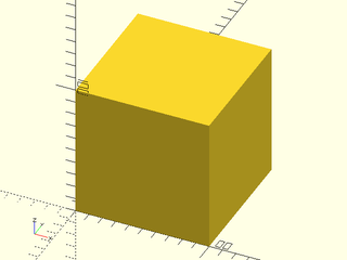
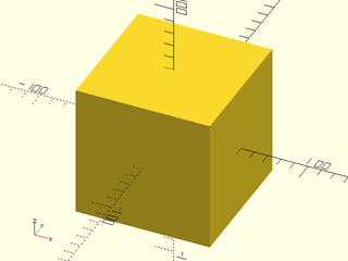
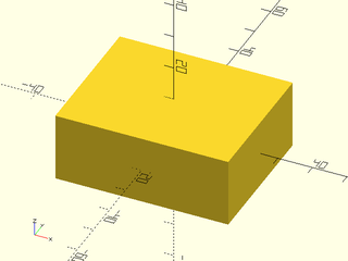
BOSL2 overrides the built-in cube() module. It still can be used as you expect from the built-in:
include <BOSL2/std.scad>
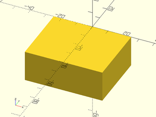
cube(100);
include <BOSL2/std.scad>
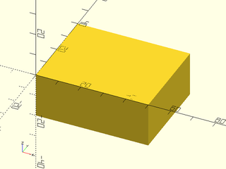
cube(100, center=true);
include <BOSL2/std.scad>
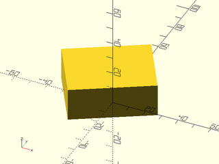
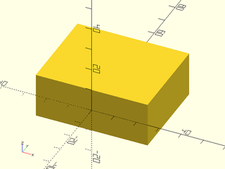
cube([50,40,20], center=true);
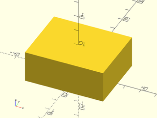
It is also enhanced to allow you to anchor, spin, orient, and attach it.
You can use anchor= similarly to how you use it with rect() or oval(),
except you can also anchor vertically in 3D, allowing anchoring to faces, edges,
and corners:
include <BOSL2/std.scad>
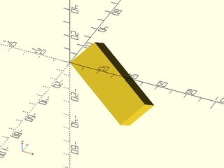
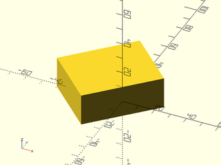
cube([50,40,20], anchor=BOTTOM);
include <BOSL2/std.scad>
cube([50,40,20], anchor=TOP+BACK);
include <BOSL2/std.scad>
cube([50,40,20], anchor=TOP+FRONT+LEFT);
You can use spin= to rotate around the Z axis after anchoring:
include <BOSL2/std.scad>
cube([50,40,20], anchor=FRONT, spin=30);
3D objects also can be given an orient= argument as a vector, pointing
to where the top of the shape should be rotated towards.
include <BOSL2/std.scad>
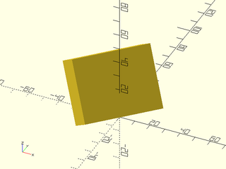
cube([50,40,20], orient=UP+BACK+RIGHT);
If you use anchor=, spin=, and orient= together, the anchor is performed
first, then the spin, then the orient:
include <BOSL2/std.scad>
cube([50,40,20], anchor=FRONT);
include <BOSL2/std.scad>
cube([50,40,20], anchor=FRONT, spin=45);
include <BOSL2/std.scad>
cube([50,40,20], anchor=FRONT, spin=45, orient=UP+FWD+RIGHT);
BOSL2 provides a cuboid() module that expands on cube(), by providing
rounding and chamfering of edges. You can use it similarly to cube(),
except that cuboid() centers by default.
You can round the edges with the rounding= argument:
include <BOSL2/std.scad>
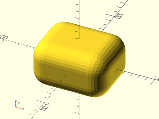
cuboid([100,80,60], rounding=20);
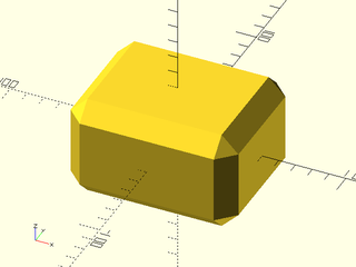
Similarly, you can chamfer the edges with the chamfer= argument:
include <BOSL2/std.scad>
cuboid([100,80,60], chamfer=10);
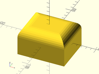
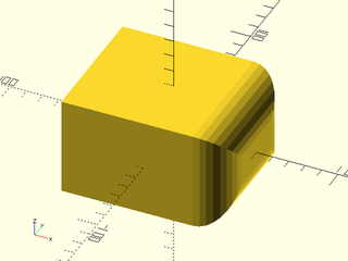
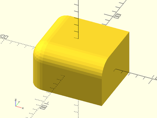
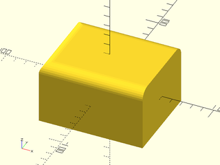
You can round only some edges, by using the edges= arguments. It can be
given a few types of arguments. If you gave it a vector pointed at a face,
it will only round the edges surrounding that face:
include <BOSL2/std.scad>
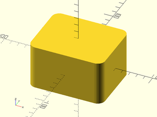
cuboid([100,80,60], rounding=20, edges=TOP);
include <BOSL2/std.scad>
cuboid([100,80,60], rounding=20, edges=RIGHT);
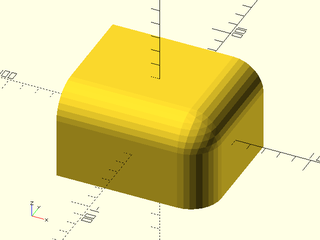
If you give edges= a vector pointing at a corner, it will round all edges
that meet at that corner:
include <BOSL2/std.scad>
cuboid([100,80,60], rounding=20, edges=RIGHT+FRONT+TOP);
include <BOSL2/std.scad>
cuboid([100,80,60], rounding=20, edges=LEFT+FRONT+TOP);
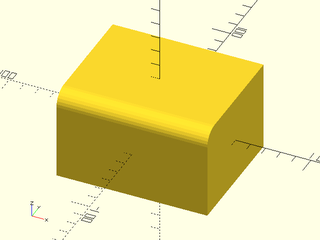
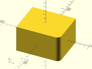
If you give edges= a vector pointing at an edge, it will round only that edge:
include <BOSL2/std.scad>
cuboid([100,80,60], rounding=10, edges=FRONT+TOP);
include <BOSL2/std.scad>
cuboid([100,80,60], rounding=10, edges=RIGHT+FRONT);
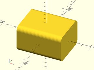
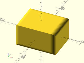
If you give the string "X", "Y", or "Z", then all edges aligned with the specified axis will be rounded:
include <BOSL2/std.scad>
cuboid([100,80,60], rounding=10, edges="X");
include <BOSL2/std.scad>
cuboid([100,80,60], rounding=10, edges="Y");
include <BOSL2/std.scad>
cuboid([100,80,60], rounding=10, edges="Z");
If you give a list of edge specs, then all edges referenced in the list will be rounded:
include <BOSL2/std.scad>
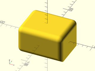
cuboid([100,80,60], rounding=10, edges=[TOP,"Z",BOTTOM+RIGHT]);
The default value for edges= is EDGES_ALL, which is all edges. You can also
give an except_edges= argument that specifies edges to NOT round:
include <BOSL2/std.scad>
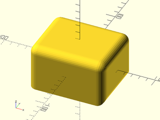
cuboid([100,80,60], rounding=10, except_edges=BOTTOM+RIGHT);
You can give the except_edges= argument any type of argument that you can
give to edges=:
include <BOSL2/std.scad>
cuboid([100,80,60], rounding=10, except_edges=[BOTTOM,"Z",TOP+RIGHT]);
You can give both edges= and except_edges=, to simplify edge specs:
include <BOSL2/std.scad>
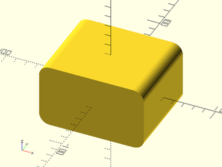
cuboid([100,80,60], rounding=10, edges=[TOP,FRONT], except_edges=TOP+FRONT);
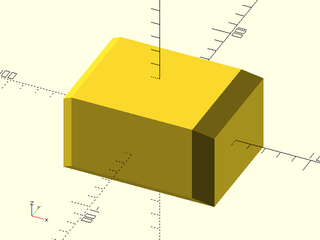
You can specify what edges to chamfer similarly:
include <BOSL2/std.scad>
cuboid([100,80,60], chamfer=10, edges=[TOP,FRONT], except_edges=TOP+FRONT);
3D Cylinder
BOSL2 overrides the built-in cylinder() module. It still can be used as you
expect from the built-in:
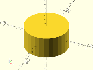
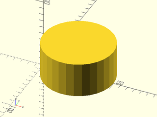
include <BOSL2/std.scad>
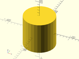
cylinder(r=50,h=50);
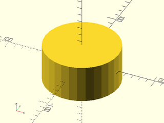
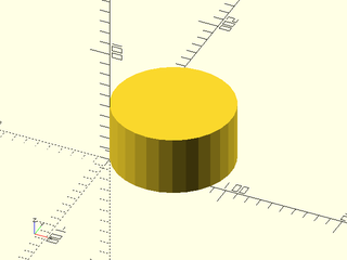
include <BOSL2/std.scad>
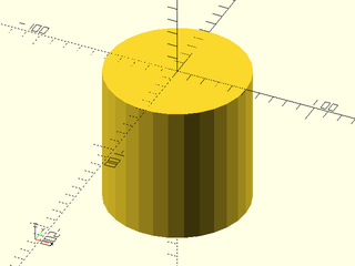
cylinder(r=50,h=50,center=true);
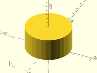
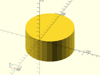
include <BOSL2/std.scad>
cylinder(d=100,h=50,center=true);
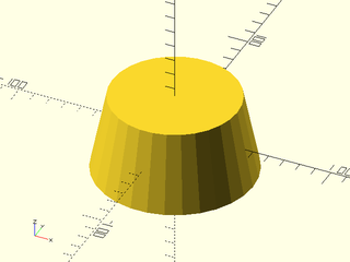
include <BOSL2/std.scad>
cylinder(d1=100,d2=80,h=50,center=true);
You can also anchor, spin, orient, and attach like the cuboid() module:
include <BOSL2/std.scad>
cylinder(r=50, h=50, anchor=TOP+FRONT);
include <BOSL2/std.scad>
cylinder(r=50, h=50, anchor=BOTTOM+LEFT);
include <BOSL2/std.scad>
cylinder(r=50, h=50, anchor=BOTTOM+LEFT, spin=30);
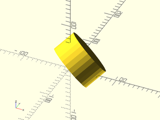
include <BOSL2/std.scad>
cylinder(r=50, h=50, anchor=BOTTOM, orient=UP+BACK+RIGHT);
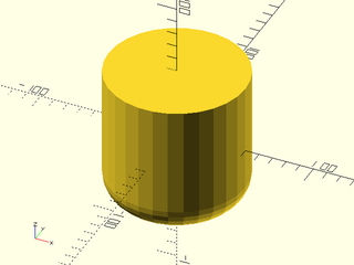
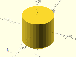
BOSL2 provides a cyl() module that expands on cylinder(), by providing
rounding and chamfering of edges. You can use it similarly to cylinder(),
except that cyl() centers the cylinder by default.
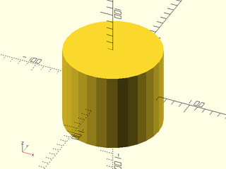
include <BOSL2/std.scad>
cyl(r=60, l=100);
include <BOSL2/std.scad>
cyl(d=100, l=100);
include <BOSL2/std.scad>
cyl(d=100, l=100, anchor=TOP);
You can round the edges with the rounding= argument:
include <BOSL2/std.scad>
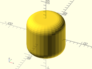
cyl(d=100, l=100, rounding=20);
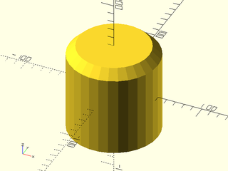
Similarly, you can chamfer the edges with the chamfer= argument:
include <BOSL2/std.scad>
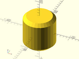
cyl(d=100, l=100, chamfer=10);
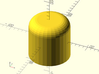
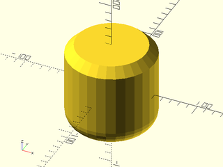
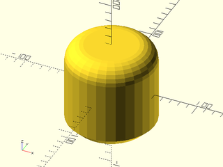
You can specify rounding and chamfering for each end individually:
include <BOSL2/std.scad>
cyl(d=100, l=100, rounding1=20);
include <BOSL2/std.scad>
cyl(d=100, l=100, rounding2=20);
include <BOSL2/std.scad>
cyl(d=100, l=100, chamfer1=10);
include <BOSL2/std.scad>
cyl(d=100, l=100, chamfer2=10);
You can even mix and match rounding and chamfering:
include <BOSL2/std.scad>
cyl(d=100, l=100, rounding1=20, chamfer2=10);
include <BOSL2/std.scad>
cyl(d=100, l=100, rounding2=20, chamfer1=10);
3D Spheres
BOSL2 overrides the built-in sphere() module. It still can be used as you
expect from the built-in:
include <BOSL2/std.scad>
sphere(r=50);
include <BOSL2/std.scad>
sphere(d=100);
You can anchor, spin, and orient sphere()s, much like you can with cylinder()
and cube():
include <BOSL2/std.scad>
sphere(d=100, anchor=FRONT);
include <BOSL2/std.scad>
sphere(d=100, anchor=FRONT, spin=30);
include <BOSL2/std.scad>
sphere(d=100, anchor=BOTTOM, orient=RIGHT+TOP);
BOSL2 also provides spheroid(), which enhances sphere() with a few features
like the circum= and style= arguments:
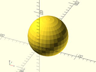
You can use the circum=true argument to force the sphere to circumscribe the
ideal sphere, as opposed to the default inscribing:
include <BOSL2/std.scad>
spheroid(d=100, circum=true);
The style= argument can choose the way that the sphere will be constructed:
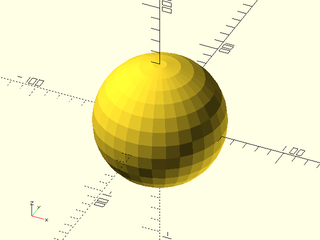
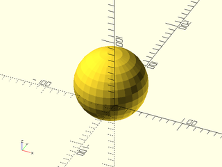
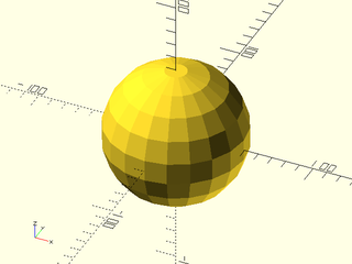
The "orig" style matches the sphere() built-in's construction.
include <BOSL2/std.scad>
spheroid(d=100, style="orig", $fn=20);
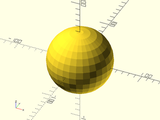
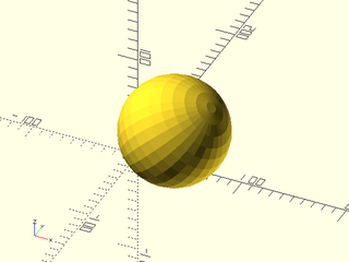
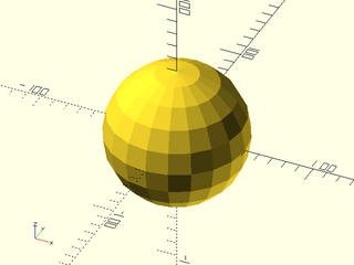
The "aligned" style will ensure that there is a vertex at each axis extrema,
so long as $fn is a multiple of 4.
include <BOSL2/std.scad>
spheroid(d=100, style="aligned", $fn=20);
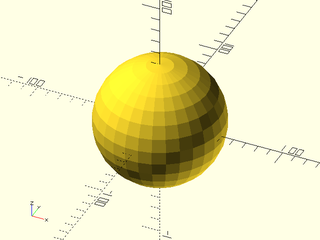
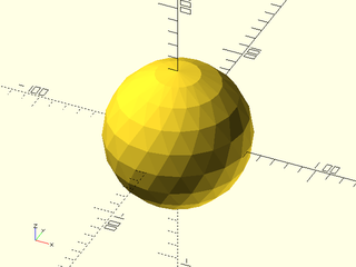
The "stagger" style will stagger the triangulation of the vertical rows:
include <BOSL2/std.scad>
spheroid(d=100, style="stagger", $fn=20);
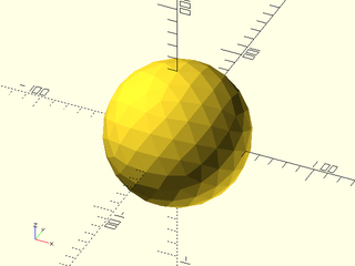
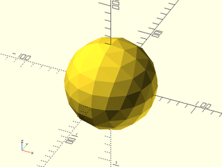
The "icosa" style will make for roughly equal-sized triangles for the entire
sphere surface, based on subdividing an icosahedron. This style will round the
effective $fn to a multiple of 5 when constructing the spheroid:
include <BOSL2/std.scad>
spheroid(d=100, style="icosa", $fn=20);
The "octa" style will also make for roughly equal-sized triangles for the entire
sphere surface, but based on subdividing an octahedron. This is useful in that it
guarantees vertices at the axis extrema. This style will round the effective $fn
to a multiple of 4 when constructing the spheroid:
include <BOSL2/std.scad>
spheroid(d=100, style="octa", $fn=20);
Indices
Table of Contents
Function Index
Topics Index
Glossary
Cheat Sheet
Tutorials
List of Files:
Basic Modeling:
- constants.scad STD
- transforms.scad STD
- attachments.scad STD
- shapes2d.scad STD
- shapes3d.scad STD
- masks.scad STD
- drawing.scad STD
- distributors.scad STD
- color.scad STD
- partitions.scad STD
- miscellaneous.scad STD
Advanced Modeling:
- paths.scad STD
- regions.scad STD
- skin.scad STD
- vnf.scad STD
- beziers.scad STD
- nurbs.scad
- rounding.scad STD
- turtle3d.scad
- isosurface.scad
Math:
- math.scad STD
- linalg.scad STD
- vectors.scad STD
- coords.scad STD
- geometry.scad STD
- trigonometry.scad STD
Data Management:
- version.scad STD
- comparisons.scad STD
- lists.scad STD
- utility.scad STD
- strings.scad STD
- structs.scad STD
- fnliterals.scad
Threaded Parts:
Parts:
- ball_bearings.scad
- cubetruss.scad
- gears.scad
- hinges.scad
- joiners.scad
- linear_bearings.scad
- modular_hose.scad
- nema_steppers.scad
- polyhedra.scad
- sliders.scad
- tripod_mounts.scad
- walls.scad
- wiring.scad
- hooks.scad
Footnotes:
STD = Included in std.scad
