Table of Contents
- LibFile: attachments.scad
- File Contents
- Section: Terminology and Shortcuts
- Subsection: Anchor
- Subsection: Spin
- Subsection: Orient
- Subsection: Specifying Directions
- Subsection: Specifying Faces
- Subsection: Specifying Edges
- Subsection: Specifying Corners
- Subsection: Anchoring of Non-Rectangular Objects and Anchor Type (atype)
- Section: Attachment Positioning
- Section: Tagging
- Section: Attachment Modifiers
- Module: diff()
- Module: tag_diff()
- Module: intersect()
- Module: tag_intersect()
- Module: conv_hull()
- Module: tag_conv_hull()
- Module: hide()
- Module: hide_this()
- Module: show_only()
- Module: show_all()
- Module: show_int()
- Section: Mask Attachment
- Module: face_mask()
- Module: edge_mask()
- Module: corner_mask()
- Module: face_profile()
- Module: edge_profile()
- Module: edge_profile_asym()
- Module: corner_profile()
- Section: Making your objects attachable
- Section: Visualizing Anchors
- Module: show_anchors()
- Module: anchor_arrow()
- Module: anchor_arrow2d()
- Module: expose_anchors()
- Module: show_transform_list()
- Module: generic_airplane()
- Module: frame_ref()
- Section: Attachable Descriptions for Operating on Attachables or Restoring a Previous State
This file contains Unicode characters that might be confused with other characters. If you think that this is intentional, you can safely ignore this warning. Use the Escape button to reveal them.
LibFile: attachments.scad
The modules in this file allows you to attach one object to another by making one object the child of another object. You can place the child object in relation to its parent object and control the position and orientation relative to the parent. The modifiers allow you to treat children in ways different from simple union, such as differencing them from the parent, or changing their color. Attachment only works when the parent and child are both written to support attachment. Also included in this file are the tools to make your own "attachable" objects.
To use, add the following lines to the beginning of your file:
include <BOSL2/std.scad>
File Contents
-
Section: Attachment Positioning
position()– Attaches children to a parent object at an anchor point. [Trans]orient()– Orients children's tops in the directon of the specified anchor. [Trans]align()– Position children with alignment to parent edges. [Trans]attach()– Attaches children to a parent object at an anchor point and with anchor orientation. [Trans]
-
tag()– Assigns a tag to an objecttag_this()– Assigns a tag to an object at the current level only.force_tag()– Assigns a tag to a non-attachable object.default_tag()– Sets a default tag for all children.tag_scope()– Creates a new tag scope.
-
diff()– Performs a differencing operation using tags rather than hierarchy to control what happens.tag_diff()– Performs adiff()and then sets a tag on the result.intersect()– Perform an intersection operation on children using tags rather than hierarchy to control what happens.tag_intersect()– Performs anintersect()and then tags the result.conv_hull()– Performs a hull operation on the children using tags to determine what happens.tag_conv_hull()– Performs aconv_hull()and then sets a tag on the result.hide()– Hides attachable children with the given tags.hide_this()– Hides attachable children at the current levelshow_only()– Show only the children with the listed tags.show_all()– Shows all children and clears tags.show_int()– Shows children with the listed tags which were already shown in the parent context.
-
face_mask()– Ataches a 3d mask shape to the given faces of the parent. [Trans]edge_mask()– Attaches a 3D mask shape to the given edges of the parent. [Trans]corner_mask()– Attaches a 3d mask shape to the given corners of the parent. [Trans]face_profile()– Extrudes a 2D edge profile into a mask for all edges and corners of the given faces on the parent. [Geom]edge_profile()– Extrudes a 2d edge profile into a mask on the given edges of the parent. [Geom]edge_profile_asym()– Extrudes an asymmetric 2D profile into a mask on the given edges and corners of the parent. [Geom]corner_profile()– Rotationally extrudes a 2d edge profile into corner mask on the given corners of the parent. [Geom]
-
Section: Making your objects attachable
attachable()– Manages the anchoring, spin, orientation, and attachments for an object.reorient()– Calculates the transformation matrix needed to reorient an object. [Trans] [Path] [VNF]named_anchor()– Creates an anchor data structure.attach_geom()– Returns the internal geometry description of an attachable object.
-
show_anchors()– Shows anchors for the parent object. [Geom]anchor_arrow()– Shows a 3d anchor orientation arrow. [Geom]anchor_arrow2d()– Shows a 2d anchor orientation arrow. [Geom]expose_anchors()– Used to show a transparent object with solid color anchor arrows.show_transform_list()– Shows a list of transforms and how they connect. [Geom]generic_airplane()– Shows a generic airplane shape, useful for viewing orientations. [Geom]frame_ref()– Shows axis orientation arrows. [Geom]
-
Section: Attachable Descriptions for Operating on Attachables or Restoring a Previous State
Section: Terminology and Shortcuts
This library adds the concept of anchoring, spin and orientation to the cube(), cylinder()
and sphere() builtins, as well as to most of the shapes provided by this library itself.
- An anchor is a place on an object which you can align the object to, or attach other objects
to using
attach()orposition(). An anchor has a position, a direction, and a spin. The direction and spin are used to orient other objects to match when usingattach(). - Spin is a simple rotation around the Z axis.
- Orientation is rotating an object so that its top is pointed towards a given vector.
An object will first be translated to its anchor position, then spun, then oriented. For a detailed step-by-step explanation of attachments, see the Attachments Tutorial.
For describing directions, faces, edges, and corners the library provides a set of shortcuts all based on combinations of unit direction vectors. You can use these for anchoring and orienting attachable objects. You can also them to specify edge sets for rounding or chamfering cuboids, or for placing edge, face and corner masks.
Subsection: Anchor
Anchoring is specified with the anchor argument in most shape modules. Specifying anchor
when creating an object will translate the object so that the anchor point is at the origin
(0,0,0). Anchoring always occurs before spin and orientation are applied.
An anchor can be referred to in one of two ways; as a directional vector, or as a named anchor string.
When given as a vector, it points, in a general way, towards the face, edge, or corner of the
object that you want the anchor for, relative to the center of the object. You can simply
specify a vector like [0,0,1] to anchor an object at the Z+ end, but you can also use
directional constants with names like TOP, BOTTOM, LEFT, RIGHT and BACK that you can add together
to specify anchor points. See specifying directions
below for the full list of pre-defined directional constants.
For example:
[0,0,1]is the same asTOPand refers to the center of the top face.[-1,0,1]is the same asTOP+LEFT, and refers to the center of the top-left edge.[1,1,-1]is the same asBOTTOM+BACK+RIGHT, and refers to the bottom-back-right corner.
When the object is cubical or rectangular in shape the anchors must have zero or one values for their components and they refer to the face centers, edge centers, or corners of the object. The direction of a face anchor will be perpendicular to the face, pointing outward. The direction of a edge anchor will be the average of the anchor directions of the two faces the edge is between. The direction of a corner anchor will be the average of the anchor directions of the three faces the corner is on.
When the object is cylindrical, conical, or spherical in nature, the anchors will be located around the surface of the cylinder, cone, or sphere, relative to the center. You can generally use an arbitrary vector to get an anchor positioned anywhere on the curved surface of such an object, and the anchor direction will be the surface normal at the anchor location. However, for anchor component pointing toward the flat face should be either -1, 1, or 0, and anchors that point diagonally toward one of the flat faces will select a point on the edge.
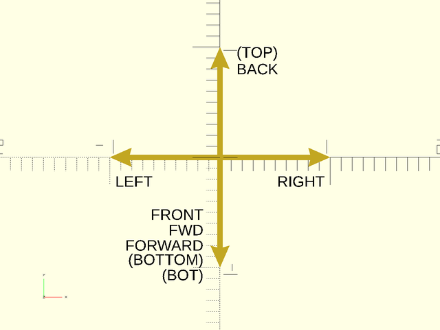
For objects in two dimensions, the natural expectation is for TOP and BOTTOM to refer to the Y direction of the shape. To support this, if you give an anchor in 2D that has anchor.y=0 then the Z component will be mapped to the Y direction. This means you can use TOP and BOTTOM for anchors of 2D objects. But remember that TOP and BOTTOM are three dimensional vectors and this is a special interpretation for 2d anchoring.
Some more complex objects, like screws and stepper motors, have named anchors to refer to places
on the object that are not at one of the standard faces, edges or corners. For example, stepper
motors have anchors for "screw1", "screw2", etc. to refer to the various screwholes on the
stepper motor shape. The names, positions, directions, and spins of these anchors are
specific to the object, and are documented when they exist.
The anchor argument is ignored if you use align() or the two-argument form of attach() because
these modules provide their own anchoring for their children.
Subsection: Spin
Spin is specified with the spin argument in most shape modules. Specifying a spin
angle when creating an object will rotate the object counter-clockwise around the Z axis by the given
number of degrees. Spin is always applied after anchoring, and before orientation.
Since spin is applied after anchoring it does not, in general, rotate around the object's center,
so it is not always what you might think of intuitively as spinning the shape.
Subsection: Orient
Orientation is specified with the orient argument in most shape modules. Specifying orient
when creating an object will rotate the object such that the top of the object will be pointed
at the vector direction given in the orient argument. Orientation is always applied after
anchoring and spin. The constants UP, DOWN, FRONT, BACK, LEFT, and RIGHT can be
added together to form the directional vector for this (e.g. LEFT+BACK). The orient parameter
is ignored when you use attach() with two arguments, because attach() provides its own orientation.
Subsection: Specifying Directions
You can use direction vectors to specify anchors for objects or to specify edges, faces, and corners of cubes. You can simply specify these direction vectors numerically, but another option is to use named constants for direction vectors. These constants define unit vectors for the six axis directions as shown below.
Figure 1.4.1: Named constants for direction vectors. Some directions have more than one name.
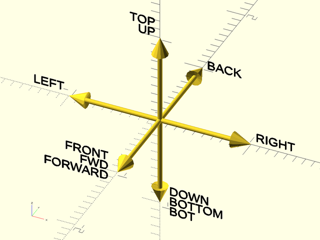
Figure 1.4.2: Named constants for direction vectors in 2D. For anchors the TOP and BOTTOM directions are collapsed into 2D as shown here, but do not try to use TOP or BOTTOM as 2D directions in other situations.
Subsection: Specifying Faces
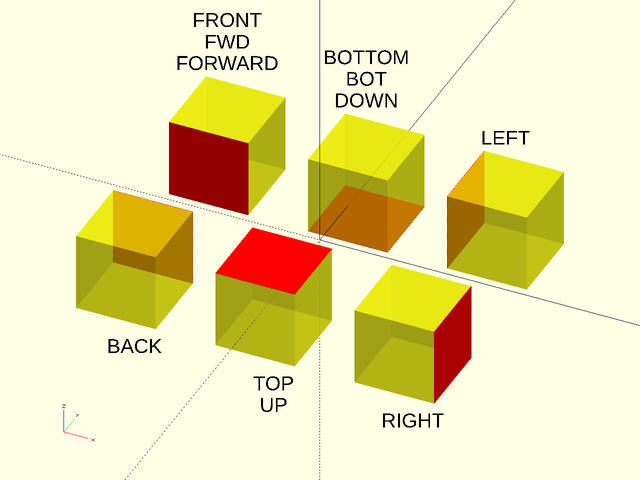
Modules operating on faces accept a list of faces to describe the faces to operate on. Each face is given by a vector that points to that face. Attachments of cuboid objects onto their faces also work by choosing an attachment face with a single vector in the same manner.
Figure 1.5.1: The six faces of the cube. Some have faces have more than one name.
Subsection: Specifying Edges
Modules operating on edges use two arguments to describe the edge set they will use: The edges argument
is a list of edge set descriptors to include in the edge set, and the except argument is a list of
edge set descriptors to remove from the edge set.
The default value for edges is "ALL", the set of all edges.
The default value for except is the empty set, meaning no edges are removed.
If either argument is just a single edge set
descriptor it can be passed directly rather than in a singleton list.
Each edge set descriptor must be one of:
- A vector pointing towards an edge, indicating that single edge.
- A vector pointing towards a face, indicating all edges surrounding that face.
- A vector pointing towards a corner, indicating all edges touching that corner.
- The string
"X", indicating all X axis aligned edges. - The string
"Y", indicating all Y axis aligned edges. - The string
"Z", indicating all Z axis aligned edges. - The string
"ALL", indicating all edges. - The string
"NONE", indicating no edges at all. - A 3x4 array, where each entry corresponds to one of the 12 edges and is set to 1 if that edge is included and 0 if the edge is not. The edge ordering is:
[
    [Y-Z-, Y+Z-, Y-Z+, Y+Z+],
    [X-Z-, X+Z-, X-Z+, X+Z+],
    [X-Y-, X+Y-, X-Y+, X+Y+]
]
You can specify edge descriptors directly by giving a vector, or you can use sums of the named direction vectors described above. Below we show all of the edge sets you can describe with sums of the direction vectors, and then we show some examples of combining edge set descriptors.
Figure 1.6.1: Vectors pointing toward an edge select that single edge
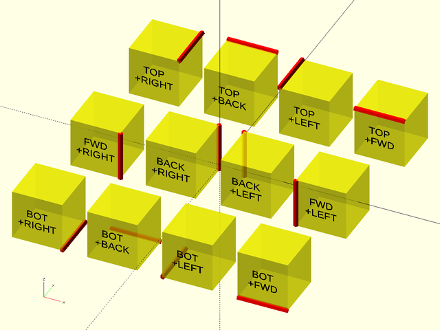
Figure 1.6.2: Vectors pointing toward a face select all edges surrounding that face.
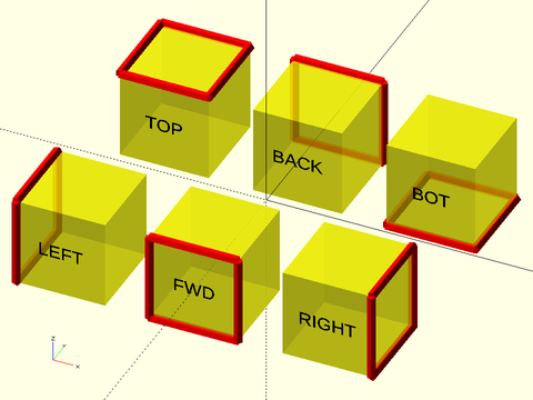
Figure 1.6.3: Vectors pointing toward a corner select all edges surrounding that corner.
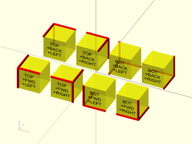
Figure 1.6.4: Named Edge Sets
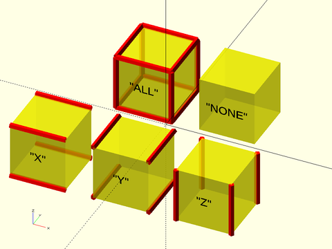
Figure 1.6.5: Next are some examples showing how you can combine edge descriptors to obtain different edge sets. You can specify the top front edge with a numerical vector or by combining the named direction vectors. If you combine them as a list you get all the edges around the front and top faces. Adding except removes an edge.
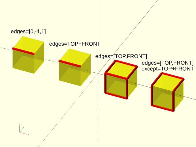
Figure 1.6.6: Using except=BACK removes the four edges surrounding the back face if they are present in the edge set. In the first example only one edge needs to be removed. In the second example we remove two of the Z-aligned edges. The third example removes all four back edges from the default edge set of all edges. You can explicitly give edges="ALL" but it is not necessary, since this is the default. In the fourth example, the edge set of Y-aligned edges contains no back edges, so the except parameter has no effect.
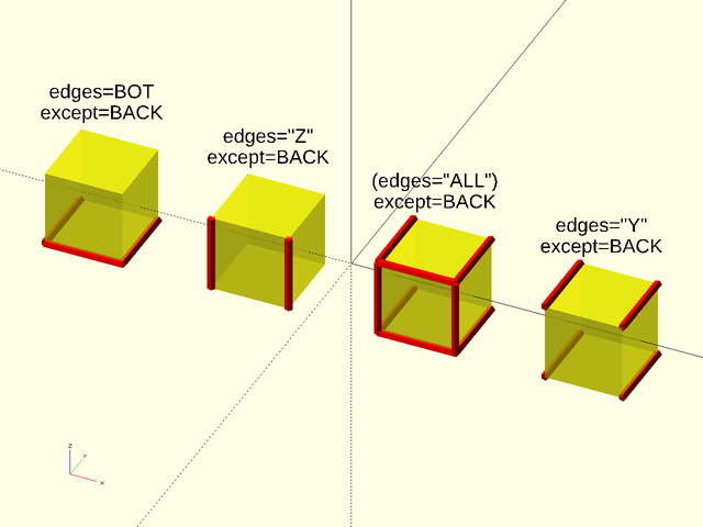
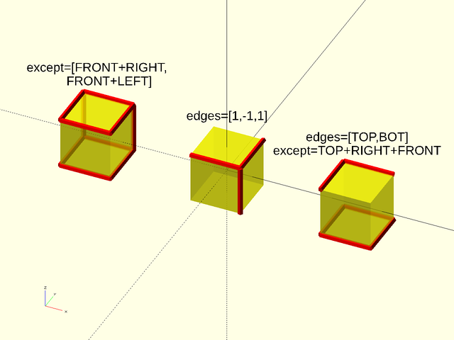
Figure 1.6.7: On the left except is a list to remove two edges. In the center we show a corner edge set defined by a numerical vector, and at the right we remove that same corner edge set with named direction vectors.
Subsection: Specifying Corners
Modules operating on corners use two arguments to describe the corner set they will use: The corners argument
is a list of corner set descriptors to include in the corner set, and the except argument is a list of
corner set descriptors to remove from the corner set.
The default value for corners is "ALL", the set of all corners.
The default value for except is the empty set, meaning no corners are removed.
If either argument is just a single corner set
descriptor it can be passed directly rather than in a singleton list.
Each corner set descriptor must be one of:
- A vector pointing towards a corner, indicating that corner.
- A vector pointing towards an edge indicating both corners at the ends of that edge.
- A vector pointing towards a face, indicating all the corners of that face.
- The string
"ALL", indicating all corners. - The string
"NONE", indicating no corners at all. - A length 8 vector where each entry corresponds to a corner and is 1 if the corner is included and 0 if it is excluded. The corner ordering is
[X-Y-Z-, X+Y-Z-, X-Y+Z-, X+Y+Z-, X-Y-Z+, X+Y-Z+, X-Y+Z+, X+Y+Z+]
You can specify corner descriptors directly by giving a vector, or you can use sums of the named direction vectors described above. Below we show all of the corner sets you can describe with sums of the direction vectors and then we show some examples of combining corner set descriptors.
Figure 1.7.1: Vectors pointing toward a corner select that corner.
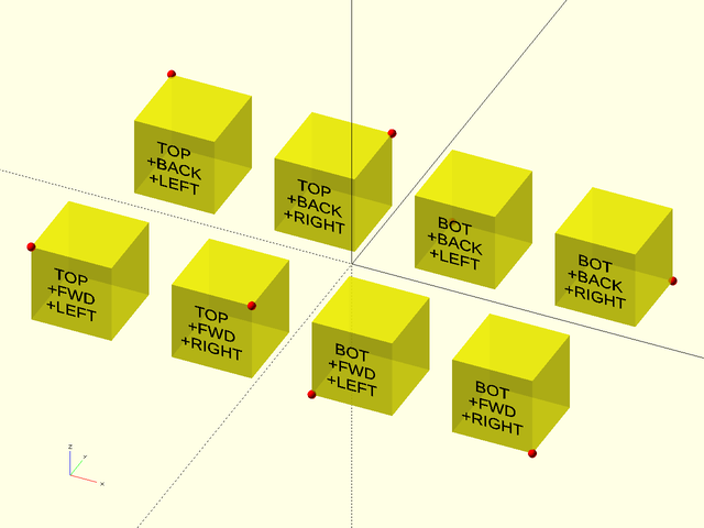
Figure 1.7.2: Vectors pointing toward an edge select the corners and the ends of the edge.
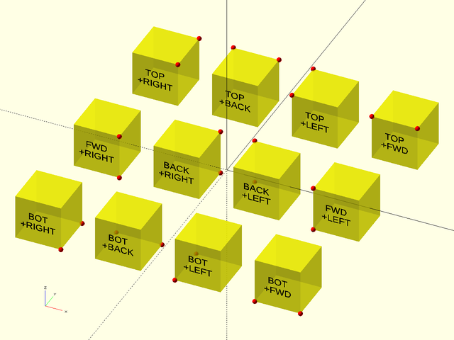
Figure 1.7.3: Vectors pointing toward a face select the corners of the face.
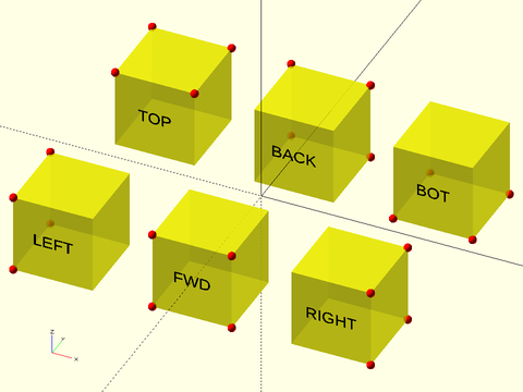
Figure 1.7.4: Corners by name
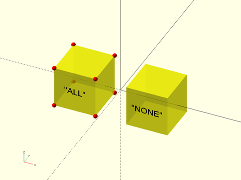
Figure 1.7.5: Next are some examples showing how you can combine corner descriptors to obtain different corner sets. You can specify corner sets numerically or by adding together named directions. The third example shows a list of two corner specifications, giving all the corners on the front face or the right face.
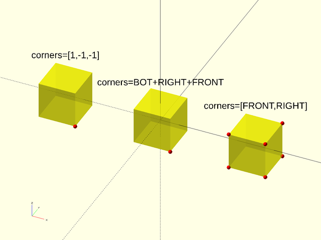
Figure 1.7.6: Corners for one edge, two edges, and all the edges except the two on one edge. Note that since the default is all edges, you only need to give the except argument in this case:
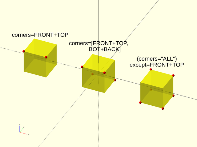
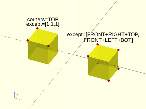
Figure 1.7.7: The first example shows a single corner removed from the top corners using a numerical vector. The second one shows removing a set of two corner descriptors from the implied set of all corners.
Subsection: Anchoring of Non-Rectangular Objects and Anchor Type (atype)
We focused above on rectangular objects that have well-defined faces and edges aligned with the coordinate axes.
Things get difficult when the objects are curved, or even when their edges are not neatly aligned with the coordinate axes.
In these cases, the library may provide multiple different anchoring schemes, called the anchor types. When a module supports
multiple anchor types, use the atype= parameter to select the anchor type you need.
Figure 1.8.1: Default "box" atype anchors for a rounded rect()
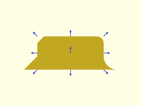
This choice enables you to position the box, or attach things to it, without regard to its rounding or chamfers. If you need to anchor onto the roundovers or chamfers then you can use the "perim" anchor type:
Figure 1.8.2: The "perim" atype for a rounded and chamfered rect()
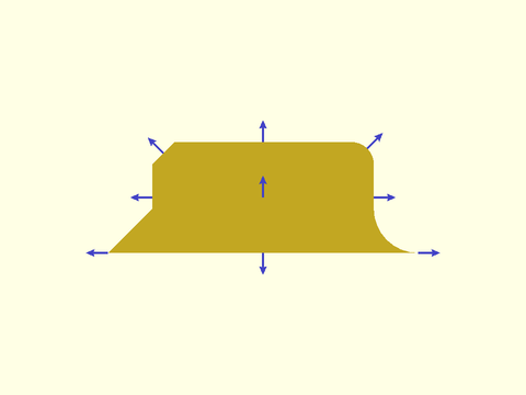
With this anchor type, the anchors are located on the perimeter. For positive roundings they point in the standard anchor direction; for negative roundings they are parallel to the base. As noted above, for circles, cylinders, and spheres, the anchor point is determined by choosing the point where the anchor vector intersects the shape. On a circle, this results in an anchor whose direction matches the user provided anchor vector. But on an ellipse, something else happens:
Figure 1.8.3: Anchors on an ellipse. The red arrow shows a TOP+RIGHT anchor direction.
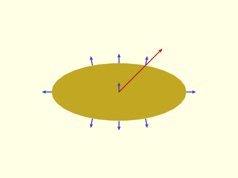
For a TOP+RIGHT anchor direction, the surface normal at the intersection point does not match the anchor direction, so the direction of the anchor shown in blue does not match the direction specified, in red. Anchors computed this way have anchor type "intersect". When a shape is concave, intersection anchors can produce a result buried inside the shape's concavity. Consider the RIGHT anchor of this supershape example:
Figure 1.8.4: A supershape with "intersect" anchor type:
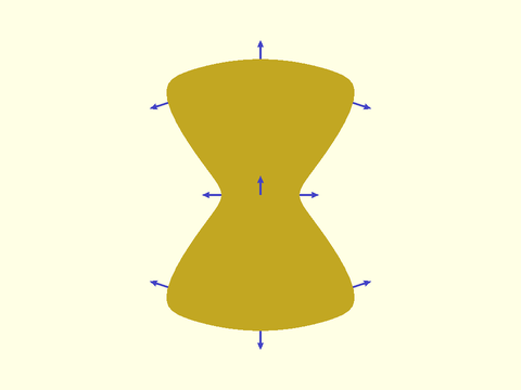
A different anchor type called "hull" finds anchors that are on the convex hull of the shape.
Figure 1.8.5: A supershape with "hull" anchor type:
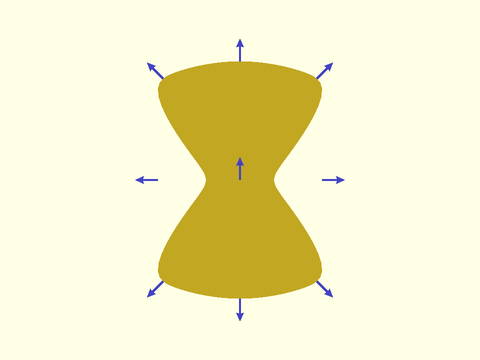
Hull anchoring works by creating the line (or plane in 3D) that is normal to the specified anchor direction, and finding the point farthest from the center that intersects that line (or plane).
Figure 1.8.6: Finding the RIGHT and BACK+LEFT "hull" anchors
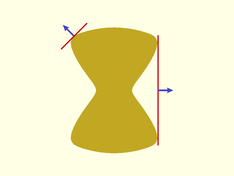
In the example the RIGHT anchor is found when the normal line (shown in red) is tangent to the shape at two points. The anchor is then taken to be the midpoint. The BACK+LEFT anchor occurs with a single tangent point, and the anchor point is located at the tangent point. For circles intersection is done to the exact circle, but for other shapes these calculations are done on the point lists that defines the shape, so if you change the number of points in the list, the precise location of the anchors can change. You can also get surprising results if your point list is badly chosen.
Figure 1.8.7: Circle anchor in blue. The red anchor is computed to a point list of a circle with 17 segments.
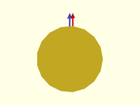
The figure shows a large horizontal offset due to a poor choice of sampling for the circular shape when using the "hull" anchor type.
The determination of "hull" or "intersect" anchors may depend on the location of the centerpoint used in the computation.
Some of the modules allow you to change the centerpoint using a cp= argument. If you need to change the centerpoint for
a module that does not provide this option, you can use the generic region() module, which will let you specify a centerpoint.
The default center point is the centroid, specified by "centroid". You can also choose "mean", which gives the mean of all
the data points, or "bbox", which gives the centerpoint of the bounding box for the data. Your last option for centerpoint is to
choose an arbitrary point that meets your needs.
Figure 1.8.8: The centerpoint for "intersect" anchors is located at the red dot
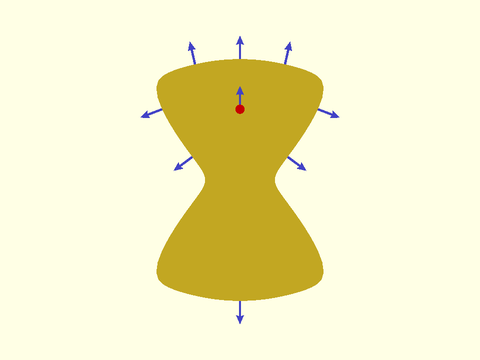
Note that all the anchors for an object have to be determined based on one anchor type and relative to the same centerpoint. The supported anchor types for each module appear in the "Anchor Types" section of its entry.
Section: Attachment Positioning
Module: position()
Synopsis: Attaches children to a parent object at an anchor point. [Trans]
Topics: Attachments
See Also: attachable(), attach(), orient()
Usage:
- PARENT() position(at) CHILDREN;
Description:
Attaches children to a parent object at an anchor point. For a step-by-step explanation of attachments, see the Attachments Tutorial.
Arguments:
| By Position | What it does |
|---|---|
at |
The vector, or name of the parent anchor point to attach to. |
Side Effects:
$attach_anchorfor eachfrom=anchor given, this is set to the[ANCHOR, POSITION, ORIENT, SPIN]information for that anchor.$attach_tois set toundef.$edge_angleis set to the angle of the edge if the anchor is on an edge and the parent is a prismoid, or vnf with "hull" anchoring$edge_lengthis set to the length of the edge if the anchor is on an edge and the parent is a prismoid, or vnf with "hull" anchoring
Example 1:
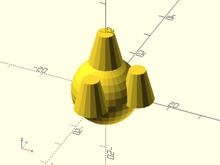
include <BOSL2/std.scad>
spheroid(d=20) {
    position(TOP) cyl(l=10, d1=10, d2=5, anchor=BOTTOM);
    position(RIGHT) cyl(l=10, d1=10, d2=5, anchor=BOTTOM);
    position(FRONT) cyl(l=10, d1=10, d2=5, anchor=BOTTOM);
}
Module: orient()
Synopsis: Orients children's tops in the directon of the specified anchor. [Trans]
Topics: Attachments
See Also: attachable(), attach(), position()
Usage:
- PARENT() orient(anchor, [spin]) CHILDREN;
Description:
Orients children such that their top is tilted in the direction of the specified parent anchor point. For a step-by-step explanation of attachments, see the Attachments Tutorial.
Arguments:
| By Position | What it does |
|---|---|
anchor |
The anchor on the parent which you want to match the orientation of. |
spin |
The spin to add to the children. (Overrides anchor spin.) |
Side Effects:
$attach_tois set toundef.
Example 1: When orienting to an anchor, the spin of the anchor may cause confusion:
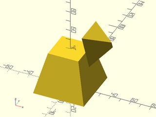
include <BOSL2/std.scad>
prismoid([50,50],[30,30],h=40) {
    position(TOP+RIGHT)
        orient(RIGHT)
            prismoid([30,30],[0,5],h=20,anchor=BOT+LEFT);
}
Example 2: You can override anchor spin with spin=.
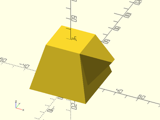
include <BOSL2/std.scad>
prismoid([50,50],[30,30],h=40) {
    position(TOP+RIGHT)
        orient(RIGHT,spin=0)
            prismoid([30,30],[0,5],h=20,anchor=BOT+LEFT);
}
Example 3: Or you can anchor the child from the back
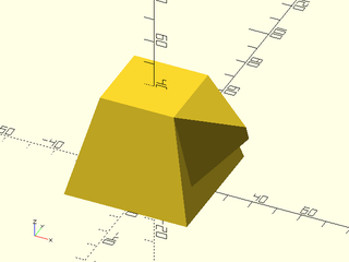
include <BOSL2/std.scad>
prismoid([50,50],[30,30],h=40) {
    position(TOP+RIGHT)
        orient(RIGHT)
            prismoid([30,30],[0,5],h=20,anchor=BOT+BACK);
}
Module: align()
Synopsis: Position children with alignment to parent edges. [Trans]
Topics: Attachments
See Also: attachable(), attach(), position(), orient()
Usage:
- PARENT() align(anchor, [align], [inside=], [inset=], [shiftout=], [overlap=]) CHILDREN;
Description:
Place a child on the face identified by anchor. If align is not given or is CENTER
then the child will be centered on top of the specified face, outside the parent object. The align parameter is a
direction defining an edge or corner to align to. The child will be aligned to that edge or corner by
choosing an appropriate anchor on the child.
Like position() this module never rotates the child. If you give anchor=RIGHT then the child
will be given the LEFT anchor and placed adjacent to the parent. You can use orient= or spin=
with the child and the alignment will adjust to select the correct child anchor. Note that if
you spin the child by an amount not a multiple of 90 degrees then an edge of the child will be
placed against the parent. This module makes it easy to place children aligned flush with the edges
of the parent, even after orienting them or spinning them. In contrast position() can
do the same thing but you would have to figure out the correct child anchor, which is not always obvious.
Because align() works by setting the child anchor, it overrides any anchor you specify to the child:
any anchor= value given to the child is ignored.
Several options can adjust how the child is positioned. You can specify inset= to inset the
aligned object from its alignment location. If you set inside=true then the
child will appear inside the parent instead of on its surface so that you can use diff() to subract it.
In this case the child recieved a default "remove" tag. The shiftout= option works with inside=true to
shift the child out by the specified distance so that the child doesn't exactly align with the parent.
Note that in the description above the anchor was said to define a "face". You can also use this module with an edge anchor, in which case a corner of the child will be placed in contact with the specified edge and the align direction will shift the child to either end of the edge. You can even give a corner as the anchor point, but in that case the only allowed alignment is CENTER.
If you give a list of anchors and/or a list of align directions then all combinations are generated.
In this way align() acts like a distributor, creating multiple copies of the child.
Named anchors are not supported by align().
Arguments:
| By Position | What it does |
|---|---|
anchor |
parent anchor or list of parent anchors for positioning children. |
align |
optional alignment direction or directions for aligning the children. Default: CENTER |
| By Name | What it does |
|---|---|
inside |
if true, place object inside the parent instead of outside. Default: false |
inset |
shift the child away from the alignment edge/corner by this amount. Default: 0 |
shiftout |
Shift an inside object outward so that it overlaps all the aligned faces. Default: 0 |
overlap |
Amount to sink the child into the parent. Defaults to $overlap which is zero by default. |
Side Effects:
$anchorset to the anchor value used for the child.$alignset to the align value used for the child.$idxset to a unique index for each child, increasing by alignment first.$attach_anchorfor each anchor given, this is set to the[ANCHOR, POSITION, ORIENT, SPIN]information for that anchor.- if
insideis true then set default tag to "remove"
Example 1: Cuboid positioned on the right of its parent. Note that it is in its native orientation.
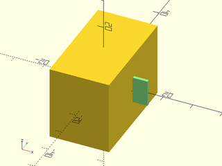
include <BOSL2/std.scad>
cuboid([20,35,25])
  align(RIGHT)
    color("lightgreen")cuboid([5,1,9]);
Example 2: Child would require anchor of RIGHT+FRONT+BOT if placed with position().
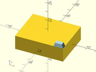
include <BOSL2/std.scad>
cuboid([50,40,15])
  align(TOP,RIGHT+FRONT)
    color("lightblue")prismoid([10,5],[7,4],height=4);
Example 3: Child requires a different anchor for each position, so a simple explicit specification of the anchor for children is impossible in this case, without using two separate commands.
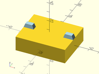
include <BOSL2/std.scad>
cuboid([50,40,15])
  align(TOP,[RIGHT,LEFT])
    color("lightblue")prismoid([10,5],[7,4],height=4);
Example 4: If you spin the child 90 deg it is still flush with the edge of the parent. In this case the required anchor for the child is BOT+FWD:
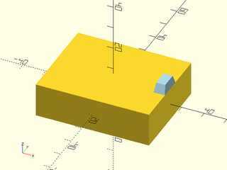
include <BOSL2/std.scad>
cuboid([50,40,15])
  align(TOP,RIGHT)
    color("lightblue")
       prismoid([10,5],[7,4],height=4,spin=90);
Example 5: Here the child is placed on the RIGHT face. Notice how the TOP+LEFT anchor of the prismoid is aligned with the edge of the parent. The prismoid remains in the same orientation.
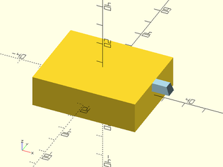
include <BOSL2/std.scad>
cuboid([50,40,15])
  align(RIGHT,TOP)
    color("lightblue")prismoid([10,5],[7,4],height=4);
Example 6: If you change the orientation of the child it still appears aligned flush in its changed orientation:
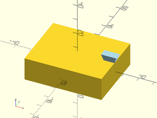
include <BOSL2/std.scad>
cuboid([50,40,15])
  align(TOP, RIGHT)
    color("lightblue")prismoid([10,5],[7,4],height=4,orient=DOWN);
Example 7: The center of the cubes edge is lined up with the center of the prismoid edge, so this result is the expected result:
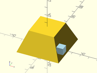
include <BOSL2/std.scad>
prismoid(50,30,25)
  align(RIGHT,FRONT)
    color("lightblue")cuboid(8);
Example 8: Spinning the cube means that the corner of the cube is the most extreme point, so that's what aligns with the front edge of the parent:
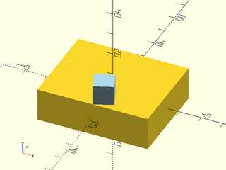
include <BOSL2/std.scad>
cuboid([50,40,15])
  align(TOP,FWD)
    color("lightblue")cuboid(9,spin=22);
Example 9: A similar thing happens if you attach a cube to a cylinder with an arbitrary anchor angle:
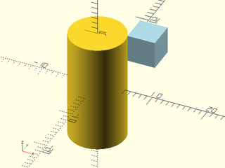
include <BOSL2/std.scad>
cyl(h=20,d=10,$fn=128)
  align([1,.3],TOP)
    color("lightblue")cuboid(5);
Example 10: Orienting the child is done in the global coordinate system (as usual) not in the parent coordinate system. Note that the blue prismoid is not lined up with the parent face. (To place the child on the face use attach().
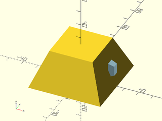
include <BOSL2/std.scad>
prismoid(50,30,25)
  align(RIGHT)
   color("lightblue")prismoid([10,5],[7,4],height=4,orient=RIGHT);
Example 11: Setting inside=true enables us to subtract the child from the parent with diff(). The "remove" tag is automatically applied when you set inside=true, and we used shiftout=0.01 to prevent z-fighting on the faces.
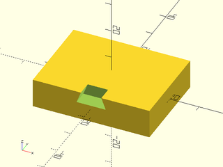
include <BOSL2/std.scad>
diff()
  cuboid([40,30,10])
    align(FRONT,TOP,inside=true,shiftout=0.01)
      prismoid([10,5],[7,5],height=4);
Example 12: Setting inset shifts all of the children away from their aligned edge, which is a different direction for each child.
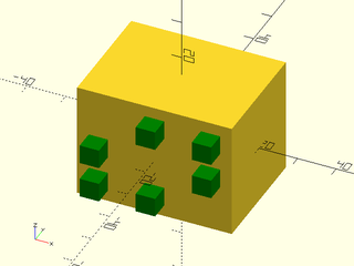
include <BOSL2/std.scad>
cuboid([40,30,30])
  align(FRONT,[TOP,BOT,LEFT,RIGHT,TOP+RIGHT,BOT+LEFT], inset=3)
    color("green") cuboid(5);
Example 13: Changing the child characteristics based on the alignment
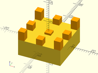
include <BOSL2/std.scad>
cuboid([20,20,8])
  align(TOP,[for(i=[-1:1], j=[-1:1]) [i,j]])
    color("orange")
      if (norm($align)==0) cuboid([3,3,1]);
      else if (norm($align)==norm([1,1])) cuboid([3,3,4.5]);
      else cuboid(3);
Example 14: In this example the pink cubes are positioned onto an edge. They meet edge-to-edge. Aligning left shifts the cube to the left end of the edge.
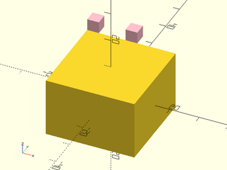
include <BOSL2/std.scad>
cuboid([30,30,20])
   align(TOP+BACK,[CTR,LEFT])
     color("pink")cuboid(4);
Example 15: Normally overlap is used to create a tiny overlap to keep CGAL happy, but you can also give it a large value as shown here:
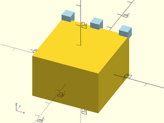
include <BOSL2/std.scad>
cuboid([30,30,20])
  align(TOP+BACK,[RIGHT,CTR,LEFT],overlap=2)
    color("lightblue")cuboid(4);
Module: attach()
Synopsis: Attaches children to a parent object at an anchor point and with anchor orientation. [Trans]
Topics: Attachments
See Also: attachable(), position(), align(), face_profile(), edge_profile(), corner_profile()
Usage:
- PARENT() attach(parent, child, [align=], [spin=], [overlap=], [inside=], [inset=], [shiftout=]) CHILDREN;
- PARENT() attach(parent, [overlap=], [spin=]) CHILDREN;
Description:
Attaches children to a parent object at an anchor point or points, oriented in the anchor direction.
This module differs from position() and align() in that it rotates the children to
the anchor direction, which generally means it places the children on the surface of a parent.
There are two modes of operation, parent anchor (single argument) and parent-child anchor (double argument).
The parent-child anchor (double argument) version is usually easier to use, and it is more powerful because it supports
alignment. You provide an anchor on the parent (parent) and an anchor on the child (child).
This module connects the child anchor on the child to the parent anchor on the parent.
Imagine pointing the parent and child anchor arrows at each other and pushing the objects
together until they meet at the anchor point. The most basic case
is attach(TOP,BOT) which puts the bottom of the child onto the top of the parent. If you
do attach(RIGHT,BOT) this puts the bottom of the child onto the right anchor of the parent.
When an object is attached to the top or bottom its BACK direction will remaing pointing BACK.
When an object is attached to one of the other anchors its FRONT will be pointed DOWN and its
BACK pointed UP. You can change this using the spin= argument to attach(). Note that this spin
rotates around the attachment vector and is not the same as the spin argument to the child, which
will usually rotate around some other direction that may be hard to predict. For 2D objects you cannot
give spin because it is not possible to spin around the attachment vector; spinning the object around the Z axis
would change the child orientation so that the anchors are no longer parallel. Furthermore, any spin
parameter you give to the child will be ignored so that the attachment condition of parallel anchors is preserved.
As with align() you can use the align= parameter to align the child to an edge or corner of the
face where that child is attached. For example attach(TOP,BOT,align=RIGHT) would stand the child
up on the top while aligning it with the right edge of the top face, and attach(RIGHT,BOT,align=TOP) which
stand the object on the right face while aligning with the top edge. If you apply spin using the
argument to attach() then it will be taken into account for the alignment. If you apply spin with
a parameter to the child it will NOT be taken into account. The special spin value "align" will
spin the child so that the child's BACK direction is pointed towards the aligned edge on the parent.
Note that spin is not permitted for
2D objects because it would change the child orientation so that the anchors are no longer parallel.
When you use align= you can also adjust the position using inset=, which shifts the child
away from the edge or corner it is aligned to.
Note that the concept of alignment doesn't always make sense for objects without corners, such as spheres or cylinders. In same cases the alignments using such children will be odd because the alignment computation is trying to place a non-existent corner somewhere. Because attach() doesn't have in formation about the child when it runs it cannot handle curved shapes differently from cubes, so this behavior cannot be changed.
If you give inside=true then the anchor arrows are lined up so they are pointing the same direction and
the child object will be located inside the parent. In this case a default "remove" tag is applied to
the children.
Because the attachment process forces an orientation and anchor point for the child, it overrides
any such specifications you give to the child: both anchor= and orient= given to the child are
ignored with the double argument version of attach(). As noted above, you can give spin= to the
child but using the spin= parameter to attach() is more likely to be useful.
For the single parameter version of attach() you give only the parent anchor. The align direction
is not permitted. In this case the child is placed at the specified parent anchor point
and rotated to the anchor direction. For example, attach(TOP) cuboid(2); will place a small
cube with its center located at the TOP anchor of the parent, so just half the cube will project
from the parent. If you want the cube sitting on the parent you need to anchor the cube to its bottom:
attach(TOP) cuboid(2,anchor=BOT);.
The single argument version of attach() respects anchor= and orient= given to the child.
These options will probably be necessary, in fact, to get the child correctly positioned. Note that
giving spin= to attach() in this case is the same as applying zrot() to the child.
You can overlap attached children into the parent by giving the $overlap value
which is 0 by default, or by the overlap= argument. This is to prevent OpenSCAD
from making non-manifold objects. You can define $overlap= as an argument in a parent
module to set the default for all attachments to it. When you give inside=true, a positive overlap
value shifts the child object outward.
If you specify an inset= value then the child is shifted away from any edges it is aligned to, towards the middle
of the parent. The shiftout= parameter is intended to simplify differences with aligned objects
placed inside the parent. It will shift the child outward along every direction where it is aligned with
the parent. For an inside child this is equivalent to giving a positive overlap and negative inset value.
For a child with inside=false it is equivalent to a negative overlap and negative inset.
For a step-by-step explanation of attachments, see the Attachments Tutorial.
Arguments:
| By Position | What it does |
|---|---|
parent |
The parent anchor point to attach to or a list of parent anchor points. |
child |
Optional child anchor point. If given, orients the child to connect this anchor point to the parent anchor. |
| By Name | What it does |
|---|---|
align |
If child is given you can specify alignment or list of alistnments to shift the child to an edge or corner of the parent. |
inset |
Shift aligned children away from their alignment edge/corner by this amount. Default: 0 |
overlap |
Amount to sink child into the parent. Equivalent to down(X) after the attach. This defaults to the value in $overlap, which is 0 by default. |
inside |
If child is given you can set inside=true to attach the child to the inside of the parent for diff() operations. Default: false |
shiftout |
Shift an inside object outward so that it overlaps all the aligned faces. Default: 0 |
spin |
Amount to rotate the parent around the axis of the parent anchor. Can set to "align" to align the child's BACK with the parent aligned edge. (Only permitted in 3D.) |
Side Effects:
$anchorset to the parent anchor value used for the child.$alignset to the align value used for the child.$idxset to a unique index for each child, increasing by alignment first.$attach_anchorfor each anchor given, this is set to the[ANCHOR, POSITION, ORIENT, SPIN]information for that anchor.- if inside is true then set default tag to "remove"
$attach_tois set to the value of thechildargument, if given. Otherwise,undef$edge_angleis set to the angle of the edge if the anchor is on an edge and the parent is a prismoid or vnf with "hull" anchoring$edge_lengthis set to the length of the edge if the anchor is on an edge and the parent is a prismoid or vnf with "hull" anchoring
Example 1: Cylinder placed on top of cube:
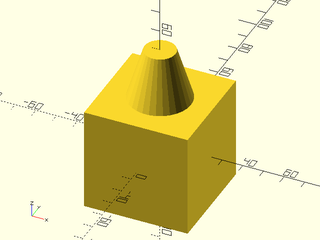
include <BOSL2/std.scad>
cuboid(50)
  attach(TOP,BOT) cylinder(d1=30,d2=15,h=25);
Example 2: Cylinder on right and front side of cube:
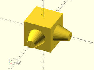
include <BOSL2/std.scad>
cuboid(50)
  attach([RIGHT,FRONT],BOT) cylinder(d1=30,d2=15,h=25);
Example 3: Using align can align child object(s) with edges
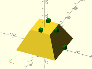
include <BOSL2/std.scad>
prismoid(50,25,25) color("green"){
  attach(TOP,BOT,align=[BACK,FWD]) cuboid(4);
  attach(RIGHT,BOT,align=[TOP,BOT]) cuboid(4);
}
Example 4: One aligned to the corner upside down (light blue) and one inset fromt the corner (pink), one aligned on a side (orange) and one rotated and aligned (green).
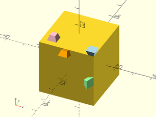
include <BOSL2/std.scad>
cuboid(30) {
  attach(TOP,TOP,align=FRONT+RIGHT) color("lightblue") prismoid(5,3,3);
  attach(TOP,BOT,inset=3,align=FRONT+LEFT) color("pink") prismoid(5,3,3);
  attach(FRONT,RIGHT,align=TOP) color("orange") prismoid(5,3,3);
  attach(FRONT,RIGHT,align=RIGHT,spin=90) color("lightgreen") prismoid(5,3,3);
}
Example 5: Rotation not a multiple of 90 degrees with alignment. The children are aligned on a corner.
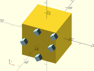
include <BOSL2/std.scad>
cuboid(30)
  attach(FRONT,BOT,spin=33,align=[RIGHT,LEFT,TOP,BOT,RIGHT+TOP])
    color("lightblue")cuboid(4);
Example 6: Anchoring the cone onto the sphere gives a single point of contact.
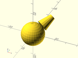
include <BOSL2/std.scad>
spheroid(d=20)
    attach([1,1.5,1], BOTTOM) cyl(l=11.5, d1=10, d2=5);
Example 7: Using the overlap option can help:
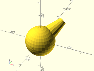
include <BOSL2/std.scad>
spheroid(d=20)
    attach([1,1.5,1], BOTTOM, overlap=1.5) cyl(l=11.5, d1=10, d2=5);
Example 8: Alignment works on the sides of cylinders but you can only align with either the top or bototm face:
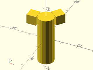
include <BOSL2/std.scad>
cyl(h=30,d=10)
  attach([LEFT,[1,1.3]], BOT,align=TOP) cuboid(6);
Example 9: Attaching to edges. The light blue and orange objects are attached to edges. The purple object is attached to an edge and aligned.
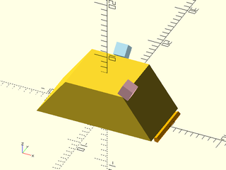
include <BOSL2/std.scad>
prismoid([20,10],[10,10],7){
  attach(RIGHT+TOP,BOT,align=FRONT) color("pink")cuboid(2);
  attach(BACK+TOP, BOT) color("lightblue")cuboid(2);
  attach(RIGHT+BOT, RIGHT) color("orange")cyl(h=8,d=1);
}
Example 10: Attaching inside the parent. For inside attachment the anchors are lined up pointing the same direction, so the most natural way to anchor the child is using its TOP anchor. This is equivalent to anchoring outside with the BOTTOM anchor and then lowering the child into the parent by its full depth.
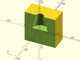
include <BOSL2/std.scad>
back_half()
  diff()
  cuboid(20)
    attach(TOP,TOP,inside=true,shiftout=0.01) cyl(d1=10,d2=5,h=10);
Example 11: Attaching inside the parent with alignment
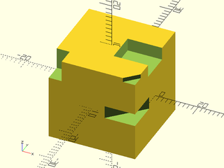
include <BOSL2/std.scad>
diff()
cuboid(20){
  attach(TOP,TOP,inside=true,align=RIGHT,shiftout=.01) cuboid([8,7,3]);
  attach(TOP,TOP,inside=true,align=LEFT+FRONT,shiftout=0.01) cuboid([3,4,5]);
  attach(RIGHT+FRONT, TOP, inside=true) cuboid([10,3,5]);
  attach(RIGHT+FRONT, TOP, inside=true, align=TOP,shiftout=.01) cuboid([5,1,2]);
}
Example 12: Attaching a 3d edge mask. Simple 2d masks can be done using edge_profile() but this mask varies along its length.
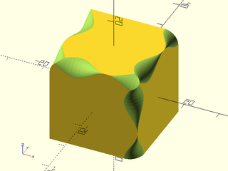
include <BOSL2/std.scad>
module wavy_edge(length,cycles, r, steps, n)
{
  rmin = is_vector(r) ? r[0] : 0.01;
  rmax = is_vector(r) ? r[1] : r;
  layers = [for(z=[0:steps])
                let(
                     r=rmin+(rmax-rmin)/2*(cos(z*360*cycles/steps)+1)
                )
                path3d( concat([[0,0]],
                               arc(corner=path2d([BACK,CTR,RIGHT]), n=n, r=r)),
                        z/steps*length-length/2)
            ];
  attachable([rmax,rmax,length]){
      skin(layers,slices=0);
      children();
  }
}
diff()
cuboid(25)
  attach([TOP+RIGHT,TOP+LEFT,TOP+FWD, FWD+RIGHT], FWD+LEFT, inside=true, shiftout=.01)
    wavy_edge(length=25.1,cycles=1.4,r=4,steps=24,n=15);
Section: Tagging
Module: tag()
Synopsis: Assigns a tag to an object
Topics: Attachments
See Also: tag_this(), force_tag(), recolor(), hide(), show_only(), diff(), intersect()
Usage:
- PARENT() tag(tag) CHILDREN;
Description:
Assigns the specified tag to all of the children. Note that if you want
to apply a tag to non-tag-aware objects you need to use force_tag() instead.
This works by setting the $tag variable, but it provides extra error checking and
handling of scopes. You may set $tag directly yourself, but this is not recommended.
For a step-by-step explanation of attachments, see the Attachments Tutorial.
Arguments:
| By Position | What it does |
|---|---|
tag |
tag string, which must not contain any spaces. |
Side Effects:
- Sets
$tagto the tag you specify, possibly with a scope prefix.
Example 1: Applies the tag to both cuboids instead of having to repeat $tag="remove" for each one.
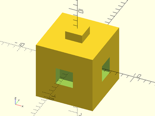
include <BOSL2/std.scad>
diff("remove")
  cuboid(10){
    position(TOP) cuboid(3);
    tag("remove")
    {
      position(FRONT) cuboid(3);
      position(RIGHT) cuboid(3);
    }
  }
Module: tag_this()
Synopsis: Assigns a tag to an object at the current level only.
Topics: Attachments
See Also: tag(), force_tag(), recolor(), hide(), show_only(), diff(), intersect()
Usage:
- PARENT() tag(tag) CHILDREN;
Description:
Assigns the specified tag to the children at the current level only, with tags reverting to
the previous tag in force for deeper descendents. This works using $tag and $save_tag.
For a step-by-step explanation of attachments, see the Attachments Tutorial.
Arguments:
| By Position | What it does |
|---|---|
tag |
tag string, which must not contain any spaces. |
Side Effects:
- Sets
$tagto the tag you specify, possibly with a scope prefix, and saves current tag in$save_tag.
Example 1: Here we subtract a cube while keeping its child. With tag() the child would inherit the "remove" tag and we would need to explicitly retag the child to prevent it from also being subtracted.
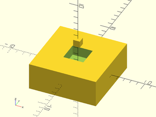
include <BOSL2/std.scad>
diff()
cuboid([10,10,4])
  tag_this("remove")position(TOP) cuboid(3)  // This cube is subtracted
    attach(TOP,BOT) cuboid(1);  // Tag is reset so this cube displays
Module: force_tag()
Synopsis: Assigns a tag to a non-attachable object.
Topics: Attachments
See Also: tag(), recolor(), hide(), show_only(), diff(), intersect()
Usage:
- PARENT() force_tag([tag]) CHILDREN;
Description:
You use this module when you want to make a non-attachable or non-BOSL2 module respect tags.
It applies to its children the tag specified (or the tag currently in force if you don't specify a tag),
making a final determination about whether to show or hide the children.
This means that tagging in children's children will be ignored.
This module is specifically provided for operating on children that are not tag aware such as modules
that don't use attachable() or built in modules such as
polygon()projection()polyhedron()(or usevnf_polyhedron())linear_extrude()(or uselinear_sweep())rotate_extrude()surface()import()difference()intersection()hull()
When you use tag-based modules like diff() with a non-attachable module, the result may be puzzling.
Any time a test occurs for display of child() that test will succeed. This means that when diff() checks
to see if it should show a module it will show it, and when diff() checks to see if it should subtract the module
it will subtract it. The result will be a hole, possibly with zero-thickness edges or faces. In order to
get the correct behavior, every non-attachable module needs an invocation of force_tag, even ones
that are not tagged.
For a step-by-step explanation of attachments, see the Attachments Tutorial.
Arguments:
| By Position | What it does |
|---|---|
tag |
tag string, which must not contain any spaces |
Side Effects:
- Sets
$tagto the tag you specify, possibly with a scope prefix.
Example 1: This example produces the full square without subtracting the "remove" item. When you use non-attachable modules with tags, results are unpredictable.

include <BOSL2/std.scad>
diff()
{
  polygon(square(10));
  move(-[.01,.01])polygon(square(5),$tag="remove");
}
Example 2: Adding force_tag() fixes the model. Note you need to add it to every non-attachable module, even the untagged ones, as shown here.

include <BOSL2/std.scad>
diff()
{
  force_tag()
    polygon(square(10));
  force_tag("remove")
    move(-[.01,.01])polygon(square(5));
}
Module: default_tag()
Synopsis: Sets a default tag for all children.
Topics: Attachments
See Also: force_tag(), recolor(), hide(), show_only(), diff(), intersect()
Usage:
- PARENT() default_tag(tag) CHILDREN;
Description:
Sets a default tag for all of the children. This is intended to be used to set a tag for a whole module
that is then used outside the module, such as setting the tag to "remove" for easy operation with diff().
The default_tag() module sets the $tag variable only if it is not already
set so you can have a module set a default tag of "remove" but that tag can be overridden by a tag()
in force from a parent. If you use tag() it will override any previously
specified tag from a parent, which can be very confusing to a user trying to change the tag on a module.
The do_tag parameter allows you to apply a default tag conditionally without having to repeat the children.
For a step-by-step explanation of attachments, see the Attachments Tutorial.
Arguments:
| By Position | What it does |
|---|---|
tag |
tag string, which must not contain any spaces. |
do_tag |
if false do not set the tag. |
Side Effects:
- Sets
$tagto the tag you specify, possibly with a scope prefix.
Example 1: The module thing() is defined with tag() and the user applied tag of "keep_it" is ignored, leaving the user puzzled.
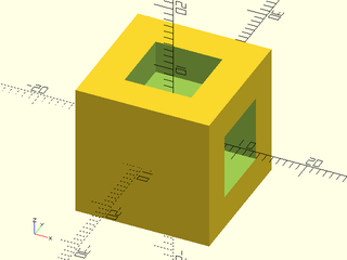
include <BOSL2/std.scad>
module thing() { tag("remove") cuboid(10);}
diff()
  cuboid(20){
    position(TOP) thing();
    position(RIGHT) tag("keep_it") thing();
}
Example 2: Using default_tag() fixes this problem: the user applied tag does not get overridden by the tag hidden in the module definition.

include <BOSL2/std.scad>
module thing() { default_tag("remove") cuboid(10);}
diff()
  cuboid(20){
    position(TOP) thing();
    position(RIGHT) tag("keep_it") thing();
}
Module: tag_scope()
Synopsis: Creates a new tag scope.
Topics: Attachments
See Also: tag(), force_tag(), default_tag()
Usage:
- tag_scope([scope]) CHILDREN;
Description:
Creates a tag scope with locally altered tag names to avoid tag name conflict with other code.
This is necessary when writing modules because the module's caller might happen to use the same tags.
Note that if you directly set the $tag variable then tag scoping will not work correctly.
Usually you will want to use tag_scope in the first child of attachable() to isolate the geometry
of your attachable object. If you put it outside the attachable() call, then it will
set a scope that also applies to the children passed to your attachable object, which is probably not what you want.
Side Effects:
$tag_prefixis set to the value ofscope=if given, otherwise is set to a random string.
Example 1: In this example, tag_scope() is required for things to work correctly.
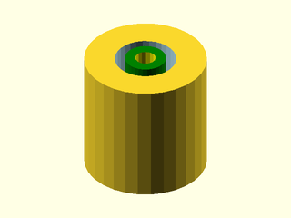
include <BOSL2/std.scad>
module myring(){
   attachable(anchor=CENTER, spin=0, d=60, l=60) {
      tag_scope()
      diff()
        cyl(d=60, l=60){
           tag("remove")
             color_this("lightblue")
             cyl(d=30, l=61);
        }
      children();
   }
}
diff()
  myring()
    color_this("green") cyl(d=20, l=61)
      tag("remove") color_this("yellow") cyl(d=10, l=65);
Example 2: Without tag_scope() we get this result

include <BOSL2/std.scad>
module myring(){
   attachable(anchor=CENTER, spin=0, d=60, l=60) {
      diff()
        cyl(d=60, l=60){
           tag("remove")
             color_this("lightblue")
             cyl(d=30, l=61);
        }
      children();
   }
}
diff()
  myring()
    color_this("green") cyl(d=20, l=61)
      tag("remove") color_this("yellow") cyl(d=10, l=65);
Example 3: If the tag_scope() is outside the attachable() call then the scope applies to the children and something different goes wrong:

include <BOSL2/std.scad>
module myring(){
   tag_scope()
   attachable(anchor=CENTER, spin=0, d=60, l=60) {
      diff()
        cyl(d=60, l=60){
           tag("remove")
             color_this("lightblue")
             cyl(d=30, l=61);
        }
      children();
   }
}
diff()
  myring()
    color_this("green") cyl(d=20, l=61)
      tag("remove") color_this("yellow") cyl(d=10, l=65);
Example 4: In this example the myring module uses "remove" tags which will conflict with use of the same tags elsewhere in a diff() operation, even without a parent-child relationship. Without the tag_scope() the result is a solid cylinder.

include <BOSL2/std.scad>
module myring(r,h,w=1,anchor,spin,orient)
{
    attachable(anchor,spin,orient,r=r,h=h){
      tag_scope("myringscope")
      diff()
        cyl(r=r,h=h)
          tag("remove") cyl(r=r-w,h=h+1);
      children();
    }
}
// Calling the module using "remove" tags
// will conflict with internal tag use in
// the myring module.
$fn=32;
diff(){
    myring(10,7,w=4);
    tag("remove")myring(8,8);
    tag("remove")diff("rem"){
       myring(9.5,8,w=1);
       tag("rem")myring(9.5,8,w=.3);
    }
  }
Section: Attachment Modifiers
Module: diff()
Synopsis: Performs a differencing operation using tags rather than hierarchy to control what happens.
Topics: Attachments
See Also: tag(), force_tag(), recolor(), show_only(), hide(), tag_diff(), intersect(), tag_intersect()
Usage:
- diff([remove], [keep]) PARENT() CHILDREN;
Description:
Performs a differencing operation using tags to control what happens. This is specifically intended to
address the situation where you want differences between a parent and child object, something
that is impossible with the native difference() module.
The children to diff are grouped into three categories, regardless of nesting level.
The remove argument is a space delimited list of tags specifying objects to
subtract. The keep argument is a similar list of tags giving objects to be kept.
Objects not matching either the remove or keep lists form the third category of base objects.
To produce its output, diff() forms the union of all the base objects and then
subtracts all the objects with tags in remove. Finally it adds in objects listed in keep.
Attachable objects should be tagged using tag()
and non-attachable objects with force_tag().
Remember when using tagged operations with that the operations don't happen in hierarchical order, since the point of tags is to break the hierarchy. If you tag an object with a keep tag, nothing will be subtracted from it, no matter where it appears because kept objects are unioned in at the end. If you want a child of an object tagged with a remove tag to stay in the model it may be better to give it a tag that is not a remove tag or a keep tag. Such an object will be subject to subtractions from other remove-tagged objects.
Note that diff() invokes its children three times.
For a step-by-step explanation of attachments, see the Attachments Tutorial.
Arguments:
| By Position | What it does |
|---|---|
remove |
String containing space delimited set of tag names of children to difference away. Default: "remove" |
keep |
String containing space delimited set of tag names of children to keep; that is, to union into the model after differencing is completed. Default: "keep" |
Example 1: Diffing using default tags

include <BOSL2/std.scad>
diff()
cuboid(50) {
    tag("remove") attach(TOP) sphere(d=40);
    tag("keep") attach(CTR) cylinder(h=40, d=10);
}
Example 2: The "hole" items are subtracted from everything else. The other tags can be anything you find convenient.
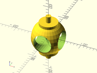
include <BOSL2/std.scad>
diff("hole")
  tag("body")sphere(d=100) {
    tag("pole") zcyl(d=55, h=100);  // attach() not needed for center-to-center.
    tag("hole") {
       xcyl(d=55, h=101);
       ycyl(d=55, h=101);
    }
    tag("axle")zcyl(d=15, h=140);
  }
Example 3:
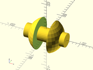
include <BOSL2/std.scad>
diff(keep="axle")
sphere(d=100) {
    tag("axle")xcyl(d=40, l=120);
    tag("remove")cuboid([40,120,100]);
}
Example 4: Masking
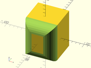
include <BOSL2/std.scad>
diff()
cube([80,90,100], center=true) {
    edge_mask(FWD)
        rounding_edge_mask(l=max($parent_size)*1.01, r=25);
}
Example 5: Here we subtract the parent object from the child. Because tags propagate to children we need to clear the "remove" tag from the child.
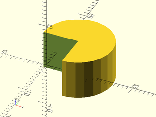
include <BOSL2/std.scad>
diff()
   tag("remove")cuboid(10)
     tag("")position(RIGHT+BACK)cyl(r=8,h=9);
Example 6: A pipe module that subtracts its interior when you call it using diff(). Normally if you union two pipes together, you'll get interfering walls at the intersection, but not here:
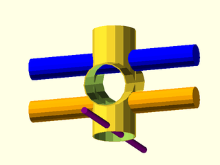
include <BOSL2/std.scad>
$fn=16;
// This module must be called by subtracting with "diff"
module pipe(length, od, id) {
    // Strip the tag the user is using to subtract
    tag("")cylinder(h=length, d=od, center=true);
    // Leave the tag alone here, so this one is removed
    cylinder(h=length+.02, d=id, center=true);
}
// Draw some intersecting pipes
diff(){
  tag("remove"){
    pipe(length=5, od=2, id=1.9);
    zrot(10)xrot(75)
      pipe(length=5, od=2, id=1.9);
  }
  // The orange bar has its center removed
  color("orange") down(1) xcyl(h=8, d=1);
  // "keep" preserves the interior of the blue bar intact
  tag("keep") recolor("blue") up(1) xcyl(h=8, d=1);
}
// Objects outside the diff don't have pipe interiors removed
color("purple") down(2.2) ycyl(h=8, d=0.3);
Example 7: Nested diff() calls work as expected, but be careful of reusing tag names, even hidden in submodules.
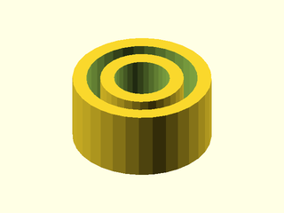
include <BOSL2/std.scad>
$fn=32;
diff("rem1")
cyl(r=10,h=10){
  diff("rem2",$tag="rem1"){
    cyl(r=8,h=11);
    tag("rem2")diff("rem3"){
        cyl(r=6,h=12);
        tag("rem3")cyl(r=4,h=13);
        }
    }
}
Example 8: This example shows deep nesting, where all the differences cross levels. Unlike the preceding example, each cylinder is positioned relative to its parent. Note that it suffices to use two remove tags, alternating between them at each level.
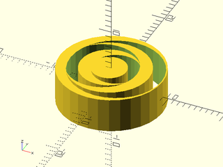
include <BOSL2/std.scad>
$fn=32;
diff("remA")
  cyl(r=9, h=6)
    tag("remA")diff("remB")
      left(.2)position(RIGHT)cyl(r=8,h=7,anchor=RIGHT)
        tag("remB")diff("remA")
         left(.2)position(LEFT)cyl(r=7,h=7,anchor=LEFT)
           tag("remA")diff("remB")
             left(.2)position(LEFT)cyl(r=6,h=8,anchor=LEFT)
               tag("remB")diff("remA")
                 right(.2)position(RIGHT)cyl(r=5,h=9,anchor=RIGHT)
                   tag("remA")diff("remB")
                     right(.2)position(RIGHT)cyl(r=4,h=10,anchor=RIGHT)
                       tag("remB")left(.2)position(LEFT)cyl(r=3,h=11,anchor=LEFT);
Example 9: When working with Non-Attachables like rotate_extrude() you must apply force_tag() to every non-attachable object.
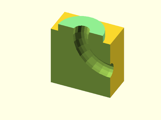
include <BOSL2/std.scad>
back_half()
  diff("remove")
    cuboid(40) {
      attach(TOP)
        recolor("lightgreen")
          cyl(l=10,d=30);
      position(TOP+RIGHT)
        force_tag("remove")
          xrot(90)
            rotate_extrude()
              right(20)
                circle(5);
    }
Example 10: Here is another example where two children are intersected using the native intersection operator, and then tagged with force_tag(). Note that because the children are at the same level, you don't need to use a tagged operator for their intersection.
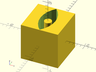
include <BOSL2/std.scad>
$fn=32;
diff()
  cuboid(10){
    force_tag("remove")intersection()
      {
        position(RIGHT) cyl(r=7,h=15);
        position(LEFT) cyl(r=7,h=15);
      }
    tag("keep")cyl(r=1,h=9);
  }
Example 11: In this example the children that are subtracted are each at different nesting levels, with a kept object in between.
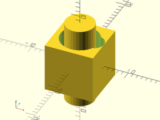
include <BOSL2/std.scad>
$fn=32;
diff()
  cuboid(10){
    tag("remove")cyl(r=4,h=11)
      tag("keep")cyl(r=3,h=17)
        tag("remove")position(RIGHT)cyl(r=2,h=18);
  }
Example 12: Combining tag operators can be tricky. Here the diff() operation keeps two tags, "fullkeep" and "keep". Then intersect() intersects the "keep" tagged item with everything else, but keeps the "fullkeep" object.
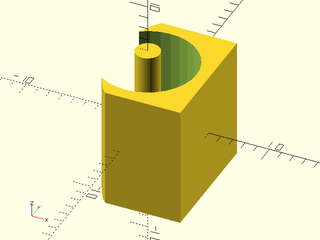
include <BOSL2/std.scad>
$fn=32;
intersect("keep","fullkeep")
  diff(keep="fullkeep keep")
    cuboid(10){
      tag("remove")cyl(r=4,h=11);
      tag("keep") position(RIGHT)cyl(r=8,h=12);
      tag("fullkeep")cyl(r=1,h=12);
  }
Example 13: In this complex example we form an intersection, subtract an object, and keep some objects. Note that for the small cylinders on either side, marking them as "keep" or removing their tag gives the same effect. This is because without a tag they become part of the intersection and the result ends up the same. For the two cylinders at the back, however, the result is different. With "keep" the cylinder on the left appears whole, but without it, the cylinder at the back right is subject to intersection.
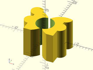
include <BOSL2/std.scad>
$fn=64;
diff()
  intersect(keep="remove keep")
    cuboid(10,$thing="cube"){
      tag("intersect"){
        position(RIGHT) cyl(r=5.5,h=15)
           tag("")cyl(r=2,h=10);
        position(LEFT) cyl(r=5.54,h=15)
           tag("keep")cyl(r=2,h=10);
      }
      // Untagged it is in the intersection
      tag("") position(BACK+RIGHT)
        cyl(r=2,h=10,anchor=CTR);
      // With keep the full cylinder appears
      tag("keep") position(BACK+LEFT)
        cyl(r=2,h=10,anchor=CTR);
      tag("remove") cyl(r=3,h=15);
    }
Module: tag_diff()
Synopsis: Performs a diff() and then sets a tag on the result.
Topics: Attachments
See Also: tag(), force_tag(), recolor(), show_only(), hide(), diff(), intersect(), tag_intersect()
Usage:
- tag_diff([tag], [remove], [keep]) PARENT() CHILDREN;
Description:
Perform a differencing operation in the manner of diff() using tags to control what happens,
and then tag the resulting difference object with the specified tag. This forces the specified
tag to be resolved at the level of the difference operation. In most cases, this is not necessary,
but if you have kept objects and want to operate on this difference object as a whole object using
more tag operations, you will probably not get the results you want if you simply use tag().
For a step-by-step explanation of attachments, see the Attachments Tutorial.
Arguments:
| By Position | What it does |
|---|---|
tag |
Tag string to apply to this difference object. Default: "" (no tag) |
remove |
String containing space delimited set of tag names of children to difference away. Default: "remove" |
keep |
String containing space delimited set of tag names of children to keep; that is, to union into the model after differencing is completed. Default: "keep" |
Side Effects:
- Sets
$tagto the tag you specify, possibly with a scope prefix.
Example 1: In this example we have a difference with a kept object that is then subtracted from a cube, but we don't want the kept object to appear in the final output, so this result is wrong:
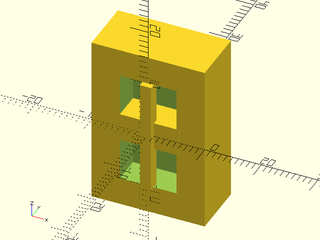
include <BOSL2/std.scad>
diff("rem"){
  cuboid([20,10,30],anchor=FRONT);
  tag("rem")diff("remove","keep"){
    cuboid([10,10,20]);
    tag("remove")cuboid([11,11,5]);
    tag("keep")cuboid([2,2,20]);
  }
}
Example 2: Using tag_diff corrects the problem:

include <BOSL2/std.scad>
diff("rem"){
  cuboid([20,10,30],anchor=FRONT);
    tag_diff("rem","remove","keep"){
      cuboid([10,10,20]);
      tag("remove")cuboid([11,11,5]);
      tag("keep")cuboid([2,2,20]);
    }
}
Example 3: This concentric cylinder example uses "keep" and produces the wrong result. The kept cylinder gets kept in the final output instead of subtracted. This happens even when we make sure to change the keep argument at the top level diff() call.

include <BOSL2/std.scad>
diff("rem","nothing")
  cyl(r=8,h=6)
    tag("rem")diff()
      cyl(r=7,h=7)
        tag("remove")cyl(r=6,h=8)
        tag("keep")cyl(r=5,h=9);
Example 4: Changing to tag_diff() causes the kept cylinder to be subtracted, producing the desired result:

include <BOSL2/std.scad>
diff("rem")
  cyl(r=8,h=6)
    tag_diff("rem")
      cyl(r=7,h=7)
        tag("remove")cyl(r=6,h=8)
        tag("keep")cyl(r=5,h=9);
Module: intersect()
Synopsis: Perform an intersection operation on children using tags rather than hierarchy to control what happens.
Topics: Attachments
See Also: tag(), force_tag(), recolor(), show_only(), hide(), diff(), tag_diff(), tag_intersect()
Usage:
- intersect([intersect], [keep]) PARENT() CHILDREN;
Description:
Performs an intersection operation on its children, using tags to
determine what happens. This is specifically intended to address
the situation where you want intersections involving a parent and
child object, something that is impossible with the native
intersection() module. This module treats the children in three
groups: objects matching the tags listed in intersect, objects
matching tags listed in keep, and the remaining objects that
don't match any of the listed tags. The intersection is computed
between the union of the intersect tagged objects and union of the objects that don't
match any of the listed tags. Finally the objects listed in keep are
unioned with the result. Attachable objects should be tagged using tag()
and non-attachable objects with force_tag().
Note that intersect() invokes its children three times.
For a step-by-step explanation of attachments, see the Attachments Tutorial.
Arguments:
| By Position | What it does |
|---|---|
intersect |
String containing space delimited set of tag names of children to intersect. Default: "intersect" |
keep |
String containing space delimited set of tag names of children to keep whole. Default: "keep" |
Example 1:
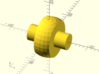
include <BOSL2/std.scad>
intersect("mask", keep="axle")
  sphere(d=100) {
      tag("mask")cuboid([40,100,100]);
      tag("axle")xcyl(d=40, l=100);
  }
Example 2: Combining tag operators can be tricky. Here the diff() operation keeps two tags, "fullkeep" and "keep". Then intersect() intersects the "keep" tagged item with everything else, but keeps the "fullkeep" object.
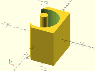
include <BOSL2/std.scad>
$fn=32;
intersect("keep","fullkeep")
  diff(keep="fullkeep keep")
    cuboid(10){
      tag("remove")cyl(r=4,h=11);
      tag("keep") position(RIGHT)cyl(r=8,h=12);
      tag("fullkeep")cyl(r=1,h=12);
  }
Example 3: In this complex example we form an intersection, subtract an object, and keep some objects. Note that for the small cylinders on either side, marking them as "keep" or removing their tag gives the same effect. This is because without a tag they become part of the intersection and the result ends up the same. For the two cylinders at the back, however, the result is different. With "keep" the cylinder on the left appears whole, but without it, the cylinder at the back right is subject to intersection.
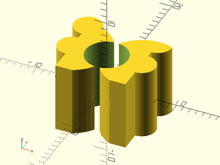
include <BOSL2/std.scad>
$fn=64;
diff()
  intersect(keep="remove keep")
    cuboid(10,$thing="cube"){
      tag("intersect"){
        position(RIGHT) cyl(r=5.5,h=15)
           tag("")cyl(r=2,h=10);
        position(LEFT) cyl(r=5.54,h=15)
           tag("keep")cyl(r=2,h=10);
      }
      // Untagged it is in the intersection
      tag("") position(BACK+RIGHT)
        cyl(r=2,h=10,anchor=CTR);
      // With keep the full cylinder appears
      tag("keep") position(BACK+LEFT)
        cyl(r=2,h=10,anchor=CTR);
      tag("remove") cyl(r=3,h=15);
    }
Module: tag_intersect()
Synopsis: Performs an intersect() and then tags the result.
Topics: Attachments
See Also: tag(), force_tag(), recolor(), show_only(), hide(), diff(), tag_diff(), intersect()
Usage:
- tag_intersect([tag], [intersect], [keep]) PARENT() CHILDREN;
Description:
Perform an intersection operation in the manner of intersect() using tags to control what happens,
and then tag the resulting difference object with the specified tag. This forces the specified
tag to be resolved at the level of the intersect operation. In most cases, this is not necessary,
but if you have kept objects and want to operate on this difference object as a whole object using
more tag operations, you will probably not get the results you want if you simply use tag().
For a step-by-step explanation of attachments, see the Attachments Tutorial.
Arguments:
| By Position | What it does |
|---|---|
tag |
Tag to set for the intersection. Default: "" (no tag) |
intersect |
String containing space delimited set of tag names of children to intersect. Default: "intersect" |
keep |
String containing space delimited set of tag names of children to keep whole. Default: "keep" |
Side Effects:
- Sets
$tagto the tag you specify, possibly with a scope prefix.
Example 1: Without tag_intersect() the kept object is not included in the difference.
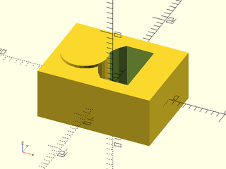
include <BOSL2/std.scad>
$fn=32;
diff()
  cuboid([20,15,9])
  tag("remove")intersect()
    cuboid(10){
      tag("intersect")position(RIGHT) cyl(r=7,h=10);
      tag("keep")position(LEFT)cyl(r=4,h=10);
    }
Example 2: Using tag_intersect corrects the problem.

include <BOSL2/std.scad>
$fn=32;
diff()
  cuboid([20,15,9])
  tag_intersect("remove")
    cuboid(10){
      tag("intersect")position(RIGHT) cyl(r=7,h=10);
      tag("keep")position(LEFT)cyl(r=4,h=10);
    }
Module: conv_hull()
Synopsis: Performs a hull operation on the children using tags to determine what happens.
Topics: Attachments, Hulling
See Also: tag(), recolor(), show_only(), hide(), diff(), intersect(), hull()
Usage:
- conv_hull([keep]) CHILDREN;
Description:
Performs a hull operation on the children using tags to determine what happens. The items
not tagged with the keep tags are combined into a convex hull, and the children tagged with the keep tags
are unioned with the result.
Note that conv_hull() invokes its children twice.
For a step-by-step explanation of attachments, see the Attachments Tutorial.
Arguments:
| By Position | What it does |
|---|---|
keep |
String containing space delimited set of tag names of children to keep out of the hull. Default: "keep" |
Example 1:
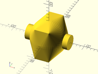
include <BOSL2/std.scad>
conv_hull("keep")
   sphere(d=100, $fn=64) {
     cuboid([40,90,90]);
     tag("keep")xcyl(d=40, l=120);
   }
Example 2: difference combined with hull where all objects are relative to each other.
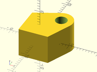
include <BOSL2/std.scad>
$fn=32;
diff()
  conv_hull("remove")
    cuboid(10)
      position(RIGHT+BACK)cyl(r=4,h=10)
        tag("remove")cyl(r=2,h=12);
Module: tag_conv_hull()
Synopsis: Performs a conv_hull() and then sets a tag on the result.
Topics: Attachments
See Also: tag(), recolor(), show_only(), hide(), diff(), intersect()
Usage:
- tag_conv_hull([tag], [keep]) CHILDREN;
Description:
Perform a convex hull operation in the manner of conv_hull() using tags to control what happens,
and then tag the resulting hull object with the specified tag. This forces the specified
tag to be resolved at the level of the hull operation. In most cases, this is not necessary,
but if you have kept objects and want to operate on the hull object as a whole object using
more tag operations, you will probably not get the results you want if you simply use tag().
For a step-by-step explanation of attachments, see the Attachments Tutorial.
Arguments:
| By Position | What it does |
|---|---|
tag |
Tag string to apply to this convex hull object. Default: "" (no tag) |
keep |
String containing space delimited set of tag names of children to keep out of the hull. Default: "keep" |
Side Effects:
- Sets
$tagto the tag you specify, possibly with a scope prefix.
Example 1: With a regular tag, the kept object is not handled as desired:

include <BOSL2/std.scad>
diff(){
   cuboid([30,30,9])
     tag("remove")conv_hull("remove")
       cuboid(10,anchor=LEFT+FRONT){
         position(RIGHT+BACK)cyl(r=4,h=10);
         tag("keep")position(FRONT+LEFT)cyl(r=4,h=10);
       }
}
Example 2: Using tag_conv_hull() fixes the problem:

include <BOSL2/std.scad>
diff(){
   cuboid([30,30,9])
     tag_conv_hull("remove")
       cuboid(10,anchor=LEFT+FRONT){
         position(RIGHT+BACK)cyl(r=4,h=10);
         tag("keep")position(FRONT+LEFT)cyl(r=4,h=10);
       }
}
Module: hide()
Synopsis: Hides attachable children with the given tags.
Topics: Attachments
See Also: tag(), recolor(), show_only(), show_all(), show_int(), diff(), intersect()
Usage:
- hide(tags) CHILDREN;
Description:
Hides all attachable children with the given tags, which you supply as a space separated string. Previously hidden objects remain hidden, so hiding is cumulative, unlike show_only().
For a step-by-step explanation of attachments, see the Attachments Tutorial.
Side Effects:
- Sets
$tags_hiddento include the tags you specify.
Example 1: Hides part of the model.
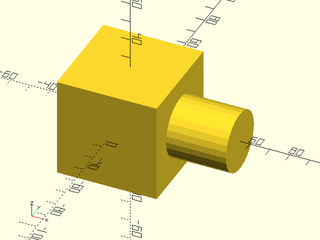
include <BOSL2/std.scad>
hide("A")
  tag("main") cube(50, anchor=CENTER, $tag="Main") {
    tag("A")attach(LEFT, BOTTOM) cylinder(d=30, h=30);
    tag("B")attach(RIGHT, BOTTOM) cylinder(d=30, h=30);
  }
Example 2: Use an invisible parent to position children. Note that children must be retagged because they inherit the parent tag.
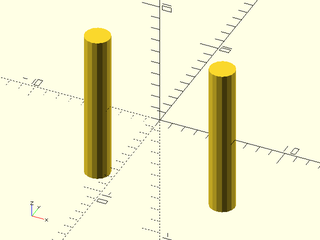
include <BOSL2/std.scad>
$fn=16;
hide("hidden")
  tag("hidden")cuboid(10)
    tag("visible") {
      position(RIGHT) cyl(r=1,h=12);
      position(LEFT) cyl(r=1,h=12);
    }
Module: hide_this()
Synopsis: Hides attachable children at the current level
Topics: Attachments
See Also: hide(), tag_this(), tag(), recolor(), show_only(), show_all(), show_int(), diff(), intersect()
Usage:
- hide_this() CHILDREN;
Description:
Hides all attachable children at the current level, while still displaying descendants. For a step-by-step explanation of attachments, see the Attachments Tutorial.
Side Effects:
- Sets
$tagand$save_tag
Example 1: Use an invisible parent to position children. Unlike with hide() we do not need to explicitly use any tags.
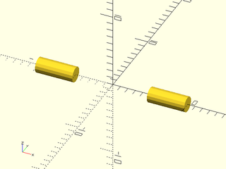
include <BOSL2/std.scad>
$fn=16;
hide_this() cuboid(10)
    {
      attach(RIGHT,BOT) cyl(r=1,h=5);
      attach(LEFT,BOT) cyl(r=1,h=5);
    }
Example 2: Nexting applications of hide_this()
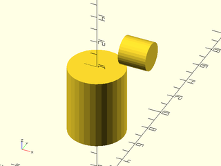
include <BOSL2/std.scad>
$fn=32;
hide_this() cuboid(10)
  attach(TOP,BOT) cyl(r=2,h=5)
    hide_this() attach(TOP,BOT) cuboid(4)
      attach(RIGHT,BOT) cyl(r=1,h=2);
Module: show_only()
Synopsis: Show only the children with the listed tags.
Topics: Attachments
See Also: tag(), recolor(), show_all(), show_int(), diff(), intersect()
Usage:
- show_only(tags) CHILDREN;
Description:
Show only the children with the listed tags, which you supply as a space separated string. Only unhidden objects will be shown, so if an object is hidden either before or after the show_only() call then it will remain hidden. This overrides any previous show_only() calls. Unlike hide(), calls to show_only() are not cumulative.
For a step-by-step explanation of attachments, see the Attachments Tutorial.
Side Effects:
- Sets
$tags_shownto the tag you specify.
Example 1: Display the attachments but not the parent
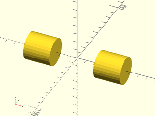
include <BOSL2/std.scad>
show_only("visible")
  cube(50, anchor=CENTER)
    tag("visible"){
      attach(LEFT, BOTTOM) cylinder(d=30, h=30);
      attach(RIGHT, BOTTOM) cylinder(d=30, h=30);
    }
Module: show_all()
Synopsis: Shows all children and clears tags.
Topics: Attachments
See Also: tag(), recolor(), show_only(), show_int(), diff(), intersect()
Description:
Shows all children. Clears the list of hidden tags and shown tags so that all child objects will be fully displayed.
Side Effects:
- Sets
$tags_shown="ALL" - Sets
$tags_hidden=[]
Module: show_int()
Synopsis: Shows children with the listed tags which were already shown in the parent context.
Topics: Attachments
See Also: tag(), recolor(), show_only(), show_all(), diff(), intersect()
Usage:
- show_int(tags) CHILDREN;
Description:
Show only the children with the listed tags which were already shown in the parent context. This intersects the current show list with the list of tags you provide.
Arguments:
| By Position | What it does |
|---|---|
tags |
list of tags to show |
Side Effects:
- Sets
$tags_shown
Section: Mask Attachment
Module: face_mask()
Synopsis: Ataches a 3d mask shape to the given faces of the parent. [Trans]
Topics: Attachments, Masking
See Also: attachable(), position(), attach(), edge_mask(), corner_mask(), face_profile(), edge_profile(), corner_profile()
Usage:
- PARENT() face_mask(faces) CHILDREN;
Description:
Takes a 3D mask shape, and attaches it to the given faces, with the appropriate orientation to be
differenced away. The mask shape should be vertically oriented (Z-aligned) with the bottom half
(Z-) shaped to be diffed away from the face of parent attachable shape. If no tag is set then
face_mask() sets the tag for children to "remove" so that it will work with the default diff() tag.
For details on specifying the faces to mask see Specifying Faces.
For a step-by-step explanation of attachments, see the Attachments Tutorial.
Arguments:
| By Position | What it does |
|---|---|
edges |
Faces to mask. See Specifying Faces for information on specifying faces. Default: All faces |
Side Effects:
- Tags the children with "remove" (and hence sets
$tag) if no tag is already set. $idxis set to the index number of each face in the list of faces given.$attach_anchoris set for each face given, to the[ANCHOR, POSITION, ORIENT, SPIN]information for that anchor.
Example 1:
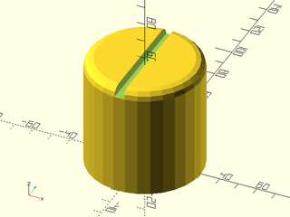
include <BOSL2/std.scad>
diff()
cylinder(r=30, h=60)
    face_mask(TOP) {
        rounding_cylinder_mask(r=30,rounding=5);
        cuboid([5,61,10]);
    }
Example 2: Using $idx
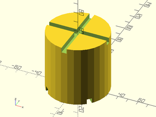
include <BOSL2/std.scad>
diff()
cylinder(r=30, h=60)
    face_mask([TOP, BOT])
        zrot(45*$idx) zrot_copies([0,90]) cuboid([5,61,10]);
Module: edge_mask()
Synopsis: Attaches a 3D mask shape to the given edges of the parent. [Trans]
Topics: Attachments, Masking
See Also: attachable(), position(), attach(), face_mask(), corner_mask(), face_profile(), edge_profile(), corner_profile()
Usage:
- PARENT() edge_mask([edges], [except]) CHILDREN;
Description:
Takes a 3D mask shape, and attaches it to the given edges of a cuboid parent, with the appropriate orientation to be
differenced away. The mask shape should be vertically oriented (Z-aligned) with the back-right
quadrant (X+Y+) shaped to be diffed away from the edge of parent attachable shape. If no tag is set
then edge_mask sets the tag for children to "remove" so that it will work with the default diff() tag.
For details on specifying the edges to mask see Specifying Edges.
For a step-by-step explanation of attachments, see the Attachments Tutorial.
Figure 5.2.1: A Typical Edge Rounding Mask
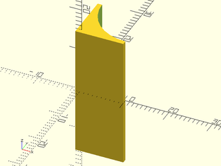
Arguments:
| By Position | What it does |
|---|---|
edges |
Edges to mask. See Specifying Edges. Default: All edges. |
except |
Edges to explicitly NOT mask. See Specifying Edges. Default: No edges. |
Side Effects:
- Tags the children with "remove" (and hence sets
$tag) if no tag is already set. $idxis set to the index number of each edge.$attach_anchoris set for each edge given, to the[ANCHOR, POSITION, ORIENT, SPIN]information for that anchor.$parent_sizeis set to the size of the parent object.
Example 1:
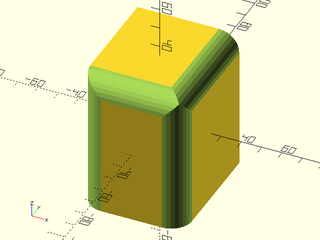
include <BOSL2/std.scad>
diff()
cube([50,60,70],center=true)
    edge_mask([TOP,"Z"],except=[BACK,TOP+LEFT])
        rounding_edge_mask(l=71,r=10);
Module: corner_mask()
Synopsis: Attaches a 3d mask shape to the given corners of the parent. [Trans]
Topics: Attachments, Masking
See Also: attachable(), position(), attach(), face_mask(), edge_mask(), face_profile(), edge_profile(), corner_profile()
Usage:
- PARENT() corner_mask([corners], [except]) CHILDREN;
Description:
Takes a 3D mask shape, and attaches it to the specified corners, with the appropriate orientation to
be differenced away. The 3D corner mask shape should be designed to mask away the X+Y+Z+ octant. If no tag is set
then corner_mask sets the tag for children to "remove" so that it will work with the default diff() tag.
See Specifying Corners for information on how to specify corner sets.
For a step-by-step explanation of attachments, see the Attachments Tutorial.
Arguments:
| By Position | What it does |
|---|---|
corners |
Corners to mask. See Specifying Corners. Default: All corners. |
except |
Corners to explicitly NOT mask. See Specifying Corners. Default: No corners. |
Side Effects:
- Tags the children with "remove" (and hence sets
$tag) if no tag is already set. $idxis set to the index number of each corner.$attach_anchoris set for each corner given, to the[ANCHOR, POSITION, ORIENT, SPIN]information for that anchor.
Example 1:
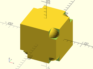
include <BOSL2/std.scad>
diff()
cube(100, center=true)
    corner_mask([TOP,FRONT],LEFT+FRONT+TOP)
        difference() {
            translate(-0.01*[1,1,1]) cube(20);
            translate([20,20,20]) sphere(r=20);
        }
Module: face_profile()
Synopsis: Extrudes a 2D edge profile into a mask for all edges and corners of the given faces on the parent. [Geom]
Topics: Attachments, Masking
See Also: attachable(), position(), attach(), edge_profile(), corner_profile(), face_mask(), edge_mask(), corner_mask()
Usage:
- PARENT() face_profile(faces, r|d=, [convexity=]) CHILDREN;
Description:
Given a 2D edge profile, extrudes it into a mask for all edges and corners bounding each given face. If no tag is set
then face_profile sets the tag for children to "remove" so that it will work with the default diff() tag.
See Specifying Faces for information on specifying faces.
For a step-by-step explanation of attachments, see the Attachments Tutorial.
Arguments:
| By Position | What it does |
|---|---|
faces |
Faces to mask edges and corners of. |
r |
Radius of corner mask. |
| By Name | What it does |
|---|---|
d |
Diameter of corner mask. |
excess |
Excess length to extrude the profile to make edge masks. Default: 0.01 |
convexity |
Max number of times a line could intersect the perimeter of the mask shape. Default: 10 |
Side Effects:
- Tags the children with "remove" (and hence sets
$tag) if no tag is already set. $idxis set to the index number of each face.$attach_anchoris set for each edge or corner given, to the[ANCHOR, POSITION, ORIENT, SPIN]information for that anchor.$profile_typeis set to"edge"or"corner", depending on what is being masked.
Example 1:
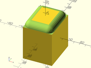
include <BOSL2/std.scad>
diff()
cube([50,60,70],center=true)
    face_profile(TOP,r=10)
        mask2d_roundover(r=10);
Module: edge_profile()
Synopsis: Extrudes a 2d edge profile into a mask on the given edges of the parent. [Geom]
Topics: Attachments, Masking
See Also: attachable(), position(), attach(), face_profile(), edge_profile_asym(), corner_profile(), edge_mask(), face_mask(), corner_mask()
Usage:
- PARENT() edge_profile([edges], [except], [convexity]) CHILDREN;
Description:
Takes a 2D mask shape and attaches it to the selected edges, with the appropriate orientation and
extruded length to be diff()ed away, to give the edge a matching profile. If no tag is set
then edge_profile sets the tag for children to "remove" so that it will work with the default diff() tag.
For details on specifying the edges to mask see Specifying Edges.
For a step-by-step
explanation of attachments, see the Attachments Tutorial.
Arguments:
| By Position | What it does |
|---|---|
edges |
Edges to mask. See Specifying Edges. Default: All edges. |
except |
Edges to explicitly NOT mask. See Specifying Edges. Default: No edges. |
excess |
Excess length to extrude the profile to make edge masks. Default: 0.01 |
convexity |
Max number of times a line could intersect the perimeter of the mask shape. Default: 10 |
Side Effects:
- Tags the children with "remove" (and hence sets
$tag) if no tag is already set. $idxis set to the index number of each edge.$attach_anchoris set for each edge given, to the[ANCHOR, POSITION, ORIENT, SPIN]information for that anchor.$profile_typeis set to"edge".$edge_angleis set to the inner angle of the current edge.
Example 1:
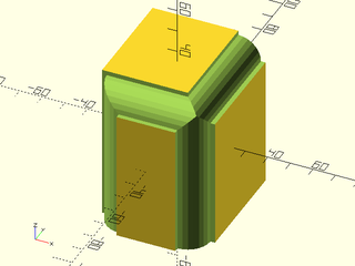
include <BOSL2/std.scad>
diff()
cube([50,60,70],center=true)
    edge_profile([TOP,"Z"],except=[BACK,TOP+LEFT])
        mask2d_roundover(r=10, inset=2);
Example 2: Using $edge_angle on a conoid
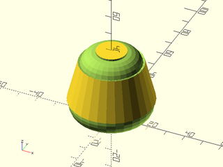
include <BOSL2/std.scad>
diff()
cyl(d1=50, d2=30, l=40, anchor=BOT) {
    edge_profile([TOP,BOT], excess=10, convexity=6) {
        mask2d_roundover(r=8, inset=1, excess=1, mask_angle=$edge_angle);
    }
}
Example 3: Using $edge_angle on a prismoid
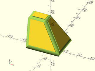
include <BOSL2/std.scad>
diff()
prismoid([60,50],[30,20],h=40,shift=[-25,15]) {
    edge_profile(excess=10, convexity=20) {
        mask2d_roundover(r=5,inset=1,mask_angle=$edge_angle,$fn=32);
    }
}
Module: edge_profile_asym()
Synopsis: Extrudes an asymmetric 2D profile into a mask on the given edges and corners of the parent. [Geom]
Topics: Attachments, Masking
See Also: attachable(), position(), attach(), face_profile(), edge_profile(), corner_profile(), edge_mask(), face_mask(), corner_mask()
Usage:
- PARENT() edge_profile([edges], [except], [convexity=], [flip=], [corner_type=]) CHILDREN;
Description:
Takes an asymmetric 2D mask shape and attaches it to the selected edges and corners, with the appropriate
orientation and extruded length to be diff()ed away, to give the edges and corners a matching profile.
If no tag is set then edge_profile_asym() sets the tag for children to "remove" so that it will work
with the default diff() tag. For details on specifying the edges to mask see Specifying Edges.
For a step-by-step explanation of attachments, see the Attachments Tutorial.
The asymmetric profiles are joined consistently at the corners. This is impossible if all three edges at a corner use the profile, hence
this situation is not permitted. The profile orientation can be inverted using the flip=true parameter.
The standard profiles are located in the first quadrant and have positive X values. If you provide a profile located in the second quadrant,
where the X values are negative, then it will produce a fillet. You can flip any of the standard profiles using xflip().
Fillets are always asymmetric because at a given edge, they can blend in two different directions, so even for symmetric profiles,
the asymmetric logic is required. You can set the corner_type parameter to select rounded, chamfered or sharp corners.
However, when the corners are inside (concave) corners, you must provide the size of the profile ([width,height]), because the
this information is required to produce the correct corner and cannot be obtain from the profile itself, which is a child object.
Arguments:
| By Position | What it does |
|---|---|
edges |
Edges to mask. See Specifying Edges. Default: All edges. |
except |
Edges to explicitly NOT mask. See Specifying Edges. Default: No edges. |
| By Name | What it does |
|---|---|
excess |
Excess length to extrude the profile to make edge masks. Default: 0.01 |
convexity |
Max number of times a line could intersect the perimeter of the mask shape. Default: 10 |
flip |
If true, reverses the orientation of any external profile parts at each edge. Default false |
corner_type |
Specifies how exterior corners should be formed. Must be one of "none", "chamfer", "round", or "sharp". Default: "none" |
size |
If given the width and height of the 2D profile, will enable rounding and chamfering of internal corners when given a negative profile. |
Side Effects:
- Tags the children with "remove" (and hence sets
$tag) if no tag is already set. $idxis set to the index number of each edge.$attach_anchoris set for each edge given, to the[ANCHOR, POSITION, ORIENT, SPIN]information for that anchor.$profile_typeis set to"edge".$edge_angleis set to the inner angle of the current edge.
Example 1:
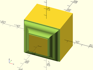
include <BOSL2/std.scad>
ogee = [
    "xstep",1,  "ystep",1,  // Starting shoulder.
    "fillet",5, "round",5,  // S-curve.
    "ystep",1,  "xstep",1   // Ending shoulder.
];
diff()
cuboid(50) {
    edge_profile_asym(FRONT)
       mask2d_ogee(ogee);
}
Example 2: Flipped
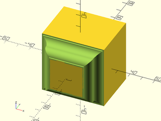
include <BOSL2/std.scad>
ogee = [
    "xstep",1,  "ystep",1,  // Starting shoulder.
    "fillet",5, "round",5,  // S-curve.
    "ystep",1,  "xstep",1   // Ending shoulder.
];
diff()
cuboid(50) {
    edge_profile_asym(FRONT, flip=true)
       mask2d_ogee(ogee);
}
Example 3: Negative Chamfering
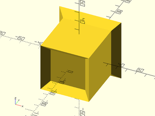
include <BOSL2/std.scad>
cuboid(50) {
    edge_profile_asym(FWD, flip=false)
        xflip() mask2d_chamfer(10);
    edge_profile_asym(BACK, flip=true, corner_type="sharp")
        xflip() mask2d_chamfer(10);
}
Example 4: Negative Roundings
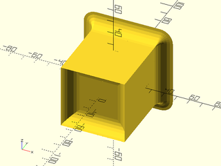
include <BOSL2/std.scad>
cuboid(50) {
    edge_profile_asym(FWD, flip=false)
        xflip() mask2d_roundover(10);
    edge_profile_asym(BACK, flip=true, corner_type="round")
        xflip() mask2d_roundover(10);
}
Example 5: Cornerless
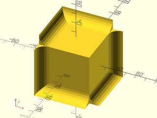
include <BOSL2/std.scad>
cuboid(50) {
    edge_profile_asym(
        "ALL", except=[TOP+FWD+RIGHT, BOT+BACK+LEFT]
     ) xflip() mask2d_roundover(10);
}
Example 6: More complicated edge sets
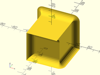
include <BOSL2/std.scad>
cuboid(50) {
    edge_profile_asym(
        [FWD,BACK,BOT+RIGHT], except=[FWD+RIGHT,BOT+BACK],
        corner_type="round"
     ) xflip() mask2d_roundover(10);
}
Example 7: Mixing it up a bit.
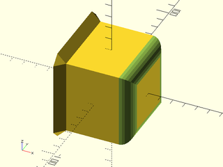
include <BOSL2/std.scad>
diff()
cuboid(60) {
    tag("keep") edge_profile_asym(LEFT, flip=true, corner_type="chamfer")
        xflip() mask2d_chamfer(10);
    edge_profile_asym(RIGHT)
        mask2d_roundover(10);
}
Example 8: Chamfering internal corners.
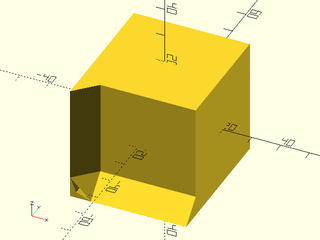
include <BOSL2/std.scad>
cuboid(40) {
    edge_profile_asym(
        [FWD+DOWN,FWD+LEFT],
        corner_type="chamfer", size=[10,10]/sqrt(2)
     ) xflip() mask2d_chamfer(10);
}
Example 9: Rounding internal corners.
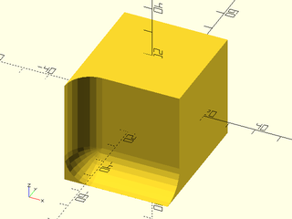
include <BOSL2/std.scad>
cuboid(40) {
    edge_profile_asym(
        [FWD+DOWN,FWD+LEFT],
        corner_type="round", size=[10,10]
     ) xflip() mask2d_roundover(10);
}
Module: corner_profile()
Synopsis: Rotationally extrudes a 2d edge profile into corner mask on the given corners of the parent. [Geom]
Topics: Attachments, Masking
See Also: attachable(), position(), attach(), face_profile(), edge_profile(), corner_mask(), face_mask(), edge_mask()
Usage:
- PARENT() corner_profile([corners], [except], [r=|d=], [convexity=]) CHILDREN;
Description:
Takes a 2D mask shape, rotationally extrudes and converts it into a corner mask, and attaches it
to the selected corners with the appropriate orientation. If no tag is set then corner_profile()
sets the tag for children to "remove" so that it will work with the default diff() tag.
See Specifying Corners for information on how to specify corner sets.
For a step-by-step explanation of attachments, see the Attachments Tutorial.
Arguments:
| By Position | What it does |
|---|---|
corners |
Corners to mask. See Specifying Corners. Default: All corners. |
except |
Corners to explicitly NOT mask. See Specifying Corners. Default: No corners. |
| By Name | What it does |
|---|---|
r |
Radius of corner mask. |
d |
Diameter of corner mask. |
convexity |
Max number of times a line could intersect the perimeter of the mask shape. Default: 10 |
Side Effects:
- Tags the children with "remove" (and hence sets
$tag) if no tag is already set. $idxis set to the index number of each corner.$attach_anchoris set for each corner given, to the[ANCHOR, POSITION, ORIENT, SPIN]information for that anchor.$profile_typeis set to"corner".
Example 1:
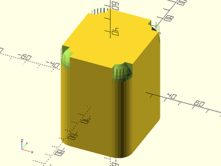
include <BOSL2/std.scad>
diff()
cuboid([50,60,70],rounding=10,edges="Z",anchor=CENTER) {
    corner_profile(TOP,r=10)
        mask2d_teardrop(r=10, angle=40);
}
Section: Making your objects attachable
Module: attachable()
Synopsis: Manages the anchoring, spin, orientation, and attachments for an object.
Topics: Attachments
See Also: reorient()
Usage: Square/Trapezoid Geometry
- attachable(anchor, spin, two_d=true, size=, [size2=], [shift=], [override=], ...) {OBJECT; children();}
Usage: Circle/Oval Geometry
- attachable(anchor, spin, two_d=true, r=|d=, ...) {OBJECT; children();}
Usage: 2D Path/Polygon Geometry
- attachable(anchor, spin, two_d=true, path=, [extent=], ...) {OBJECT; children();}
Usage: 2D Region Geometry
- attachable(anchor, spin, two_d=true, region=, [extent=], ...) {OBJECT; children();}
Usage: Cubical/Prismoidal Geometry
- attachable(anchor, spin, [orient], size=, [size2=], [shift=], [override=], ...) {OBJECT; children();}
Usage: Cylindrical Geometry
- attachable(anchor, spin, [orient], r=|d=, l=, [axis=], ...) {OBJECT; children();}
Usage: Conical Geometry
- attachable(anchor, spin, [orient], r1=|d1=, r2=|d2=, l=, [axis=], ...) {OBJECT; children();}
Usage: Spheroid/Ovoid Geometry
- attachable(anchor, spin, [orient], r=|d=, ...) {OBJECT; children();}
Usage: Extruded Path/Polygon Geometry
- attachable(anchor, spin, path=, l=|h=, [extent=], ...) {OBJECT; children();}
Usage: Extruded Region Geometry
- attachable(anchor, spin, region=, l=|h=, [extent=], ...) {OBJECT; children();}
Usage: VNF Geometry
- attachable(anchor, spin, [orient], vnf=, [extent=], ...) {OBJECT; children();}
Usage: Pre-Specified Geometry
- attachable(anchor, spin, [orient], geom=) {OBJECT; children();}
Description:
Manages the anchoring, spin, orientation, and attachments for OBJECT, located in a 3D volume or 2D area.
A managed 3D volume is assumed to be vertically (Z-axis) oriented, and centered.
A managed 2D area is just assumed to be centered. The shape to be managed is given
as the first child to this module, and the second child should be given as children().
For example, to manage a conical shape:
attachable(anchor, spin, orient, r1=r1, r2=r2, l=h) {
    cyl(r1=r1, r2=r2, l=h);
    children();
}
If this is not run as a child of attach() with the to argument
given, then the following transformations are performed in order:
- Translates so the
anchorpoint is at the origin (0,0,0). - Rotates around the Z axis by
spindegrees counter-clockwise. - Rotates so the top of the part points towards the vector
orient.
If this is called as a child of attach(from,to), then the info
for the anchor points referred to by from and to are fetched,
which will include position, direction, and spin. With that info,
the following transformations are performed:
- Translates this part so its anchor position matches the parent's anchor position.
- Rotates this part so its anchor direction vector exactly opposes the parent's anchor direction vector.
- Rotates this part so its anchor spin matches the parent's anchor spin.
In addition to handling positioning of the attachable object,
this module is also responsible for handing coloring of objects with recolor() and color_this(), and
it is responsible for processing tags and determining whether the object should
display or not in the current context. The determination based on the tags of whether to display the attachable object
often occurs in this module, which means that an object which does not display (e.g. a "remove" tagged object
inside diff()) cannot have internal tag() calls that change its tags and cause submodel
portions to display: the entire object simply does not run. If you want the use the attachable object's internal tags outside
of the attachable object you can set expose_tags=true which delays the determination to display objects to the children.
For this to work correctly, all of the children must be attachables. An example situation where you should set
expose_tags=true is when you want to have negative space in an attachable object that gets removed from the parent via
a "remove" tagged component of your attachable.
Application of recolor() and color_this() also happens in this module and normally it applies to the
entire attachable object, so coloring commands that you give internally in the first child to attachable() have no effect.
Generally it makes sense that if a user specifies a color for an attachable object, the entire object is displayed
in that color, but if you want to retain control of color for sub-parts of an attachable object, you can use
the keep_color=true option, which delays the assignment of colors to the child level. For this to work
correctly, all of the sub-parts of your attachable object must be attachables. Also note that this option could
be confusing to users who don't understand why color commands are not working on the object.
Note that anchors created by attachable() are generally intended for use by the user-supplied children of the attachable object, but they are available internally and can be used in the object's definition.
For a step-by-step explanation of attachments, see the Attachments Tutorial.
Arguments:
| By Position | What it does |
|---|---|
anchor |
Translate so anchor point is at origin (0,0,0). See anchor. Default: CENTER |
spin |
Rotate this many degrees around the Z axis after anchor. See spin. Default: 0 |
orient |
Vector to rotate top towards, after spin. See orient. Default: UP |
| By Name | What it does |
|---|---|
size |
If given as a 3D vector, contains the XY size of the bottom of the cuboidal/prismoidal volume, and the Z height. If given as a 2D vector, contains the front X width of the rectangular/trapezoidal shape, and the Y length. |
size2 |
If given as a 2D vector, contains the XY size of the top of the prismoidal volume. If given as a number, contains the back width of the trapezoidal shape. |
shift |
If given as a 2D vector, shifts the top of the prismoidal or conical shape by the given amount. If given as a number, shifts the back of the trapezoidal shape right by that amount. Default: No shift. |
r |
Radius of the cylindrical/conical volume. Can be a scalar, or a list of sizes per axis. |
d |
Diameter of the cylindrical/conical volume. Can be a scalar, or a list of sizes per axis. |
r1 |
Radius of the bottom of the conical volume. Can be a scalar, or a list of sizes per axis. |
r2 |
Radius of the top of the conical volume. Can be a scalar, or a list of sizes per axis. |
d1 |
Diameter of the bottom of the conical volume. Can be a scalar, a list of sizes per axis. |
d2 |
Diameter of the top of the conical volume. Can be a scalar, a list of sizes per axis. |
l / h |
Length of the cylindrical, conical, or extruded path volume along axis. |
vnf |
The VNF of the volume. |
path |
The path to generate a polygon from. |
region |
The region to generate a shape from. |
extent |
If true, calculate anchors by extents, rather than intersection, for VNFs and paths. Default: true. |
cp |
If given, specifies the centerpoint of the volume. Default: [0,0,0] |
offset |
If given, offsets the perimeter of the volume around the centerpoint. |
anchors |
If given as a list of anchor points, allows named anchor points. |
two_d |
If true, the attachable shape is 2D. If false, 3D. Default: false (3D) |
axis |
The vector pointing along the axis of a geometry. Default: UP |
override |
Function that takes an anchor and for 3d returns a triple [position, direction, spin] or for 2d returns a pair [position,direction] to use for that anchor to override the normal one. You can also supply a lookup table that is a list of [anchor, [position, direction, spin]] entries. If the direction/position/spin that is returned is undef then the default will be used. This option applies only to the "trapezoid" and "prismoid" geometry types. |
geom |
If given, uses the pre-defined (via attach_geom() geometry. |
expose_tags |
If true then delay the decision to display or not display this object to the children, which it possible for tags to respond to operations like diff() used outside the attachble object. Only works correctly if everything in the attachable is also attachable. Default: false |
keep_color |
If true then delay application of color to the children, which means that externally applied color is overridden by color specified within the attachable. Only works properly if everything in the attachable is also attacahble. Default: false |
Side Effects:
$parent_anchoris set to the parent object'sanchorvalue.$parent_spinis set to the parent object'sspinvalue.$parent_orientis set to the parent object'sorientvalue.$parent_geomis set to the parent object'sgeomvalue.$parent_sizeis set to the parent object's cubical[X,Y,Z]volume size.$coloris used to set the color of the object$save_coloris used to revert color to the parent's color
Example 1: Cubical Shape
include <BOSL2/std.scad>
attachable(anchor, spin, orient, size=size) {
    cube(size, center=true);
    children();
}
Example 2: Prismoidal Shape
include <BOSL2/std.scad>
attachable(
    anchor, spin, orient,
    size=point3d(botsize,h),
    size2=topsize,
    shift=shift
) {
    prismoid(botsize, topsize, h=h, shift=shift);
    children();
}
Example 3: Cylindrical Shape, Z-Axis Aligned
include <BOSL2/std.scad>
attachable(anchor, spin, orient, r=r, l=h) {
    cyl(r=r, l=h);
    children();
}
Example 4: Cylindrical Shape, Y-Axis Aligned
include <BOSL2/std.scad>
attachable(anchor, spin, orient, r=r, l=h, axis=BACK) {
    cyl(r=r, l=h);
    children();
}
Example 5: Cylindrical Shape, X-Axis Aligned
include <BOSL2/std.scad>
attachable(anchor, spin, orient, r=r, l=h, axis=RIGHT) {
    cyl(r=r, l=h);
    children();
}
Example 6: Conical Shape, Z-Axis Aligned
include <BOSL2/std.scad>
attachable(anchor, spin, orient, r1=r1, r2=r2, l=h) {
    cyl(r1=r1, r2=r2, l=h);
    children();
}
Example 7: Conical Shape, Y-Axis Aligned
include <BOSL2/std.scad>
attachable(anchor, spin, orient, r1=r1, r2=r2, l=h, axis=BACK) {
    cyl(r1=r1, r2=r2, l=h);
    children();
}
Example 8: Conical Shape, X-Axis Aligned
include <BOSL2/std.scad>
attachable(anchor, spin, orient, r1=r1, r2=r2, l=h, axis=RIGHT) {
    cyl(r1=r1, r2=r2, l=h);
    children();
}
Example 9: Spherical Shape
include <BOSL2/std.scad>
attachable(anchor, spin, orient, r=r) {
    sphere(r=r);
    children();
}
Example 10: Extruded Polygon Shape, by Extents
include <BOSL2/std.scad>
attachable(anchor, spin, orient, path=path, l=length) {
    linear_extrude(height=length, center=true)
        polygon(path);
    children();
}
Example 11: Extruded Polygon Shape, by Intersection
include <BOSL2/std.scad>
attachable(anchor, spin, orient, path=path, l=length, extent=false) {
    linear_extrude(height=length, center=true)
        polygon(path);
    children();
}
Example 12: Arbitrary VNF Shape, by Extents
include <BOSL2/std.scad>
attachable(anchor, spin, orient, vnf=vnf) {
    vnf_polyhedron(vnf);
    children();
}
Example 13: Arbitrary VNF Shape, by Intersection
include <BOSL2/std.scad>
attachable(anchor, spin, orient, vnf=vnf, extent=false) {
    vnf_polyhedron(vnf);
    children();
}
Example 14: 2D Rectangular Shape
include <BOSL2/std.scad>
attachable(anchor, spin, orient, two_d=true, size=size) {
    square(size, center=true);
    children();
}
Example 15: 2D Trapezoidal Shape
include <BOSL2/std.scad>
attachable(
    anchor, spin, orient,
    two_d=true,
    size=[x1,y],
    size2=x2,
    shift=shift
) {
    trapezoid(w1=x1, w2=x2, h=y, shift=shift);
    children();
}
Example 16: 2D Circular Shape
include <BOSL2/std.scad>
attachable(anchor, spin, orient, two_d=true, r=r) {
    circle(r=r);
    children();
}
Example 17: Arbitrary 2D Polygon Shape, by Extents
include <BOSL2/std.scad>
attachable(anchor, spin, orient, two_d=true, path=path) {
    polygon(path);
    children();
}
Example 18: Arbitrary 2D Polygon Shape, by Intersection
include <BOSL2/std.scad>
attachable(anchor, spin, orient, two_d=true, path=path, extent=false) {
    polygon(path);
    children();
}
Example 19: Using Pre-defined Geometry
include <BOSL2/std.scad>
geom = atype=="perim"? attach_geom(two_d=true, path=path, extent=false) :
    atype=="extents"? attach_geom(two_d=true, path=path, extent=true) :
    atype=="circle"? attach_geom(two_d=true, r=r) :
    assert(false, "Bad atype");
attachable(anchor, spin, orient, geom=geom) {
    polygon(path);
    children();
}
Example 20: An object can be designed to attach as negative space using diff(), but if you want an object to include both positive and negative space then you run into trouble because tags inside the attachable() are ignored. One solution is to call attachable() twice. This example shows how two calls to attachable can create an object with positive and negative space. Note, however, that children in the negative space are differenced away: the highlighted little cube does not survive into the final model.
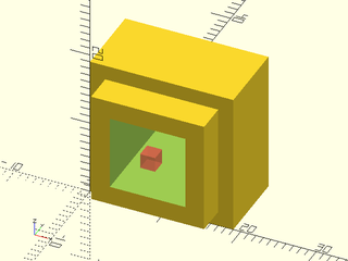
include <BOSL2/std.scad>
module thing(anchor,spin,orient) {
   tag("remove") attachable(size=[15,15,15],anchor=anchor,spin=spin,orient=orient){
     cuboid([10,10,16]);
     union(){}   // dummy children
   }
   attachable(size=[15,15,15], anchor=anchor, spin=spin, orient=orient){
     cuboid([15,15,15]);
     children();
   }
}
diff()
  cube([19,10,19])
    attach([FRONT],overlap=-4)
      thing(anchor=TOP)
        # attach(TOP) cuboid(2,anchor=TOP);
Example 21: Here is an example where the "keep" tag allows children to appear in the negative space. That tag is also needed for this module to produce the desired output. As above, the tag must be applied outside the attachable() call.
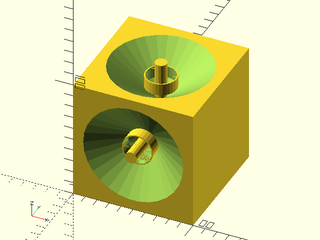
include <BOSL2/std.scad>
module thing(anchor = CENTER, spin = 0, orient = UP) {
   tag("remove") attachable(anchor, spin, orient, d1=0,d2=95,h=33) {
       cylinder(h = 33.1, d1 = 0, d2 = 95, anchor=CENTER);
       union(){}  // dummy children
   }
   tag("keep") attachable(anchor, spin, orient,d1=0,d2=95,h=33) {
         cylinder(h = 33, d = 10,anchor=CENTER);
         children();
     }
 }
 diff()
   cube(100)
     attach([FRONT,TOP],overlap=-4)
       thing(anchor=TOP)
         tube(ir=12,h=10);
Example 22: A different way to achieve similar effects to the above to examples is to use the expose_tags parameter. This parameter allows you to use just one call to attachable. The second example above can also be rewritten like this.
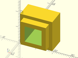
include <BOSL2/std.scad>
module thing(anchor,spin,orient) {
   attachable(size=[15,15,15],anchor=anchor,spin=spin,orient=orient,expose_tags=true){
     union(){
       cuboid([15,15,15]);
       tag("remove")cuboid([10,10,16]);
     }
     children();
   }
}
diff()
  cube([19,10,19])
    attach([FRONT],overlap=-4)
      thing(anchor=TOP);
Example 23: An advantage of using expose_tags is that it can work on nested constructions. Here the child cylinder is aligned relative to its parent and removed from the calling parent object.
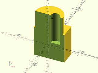
include <BOSL2/std.scad>
$fn=64;
module thing(anchor=BOT){
  attachable(anchor = anchor,d=9,h=6,expose_tags=true){
    cyl(d = 9, h = 6)
      tag("remove")
         align(RIGHT+TOP,inside=true)
              left(1)up(1)cyl(l=11, d=3);
    children();
  }
}
back_half()
  diff()
    cuboid(10)
      position(TOP)thing(anchor=BOT);
Example 24: Here an attachable module uses recolor() to change the color of a sub-part, producing the result shown on the left. But if the caller applies color to the attachable, then both the green and yellow are changed, as shown on the right.
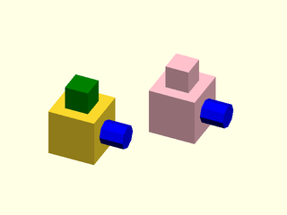
include <BOSL2/std.scad>
module thing(anchor=CENTER) {
    attachable(anchor,size=[10,10,10]) {
        cuboid(10)
          position(TOP) recolor("green")
            cuboid(5,anchor=BOT);
        children();
    }
}
move([-15,-15])
thing()
  attach(RIGHT,BOT)
    recolor("blue") cyl(d=5,h=5);
recolor("pink") thing()
  attach(RIGHT,BOT)
    recolor("blue") cyl(d=5,h=5);
Example 25: Using the keep_color=true option enables the green color to persist, even when the user specifies a color.
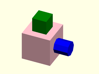
include <BOSL2/std.scad>
module thing(anchor=CENTER) {
    attachable(anchor,size=[10,10,10],keep_color=true) {
        cuboid(10)
          position(TOP) recolor("green")
            cuboid(5,anchor=BOT);
        children();
    }
}
recolor("pink") thing()
  attach(RIGHT,BOT)
    recolor("blue") cyl(d=5,h=5);
Example 26: This example defines named anchors and then uses them internally in the object definition to make a cutout in the socket() object and to attach the plug on the plug() object. These objects can be connected using the "socket" and "plug" named anchors, which will fit the plug into the socket.
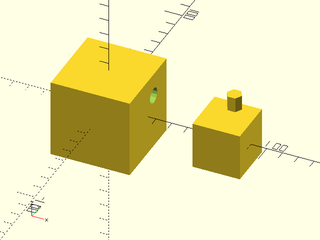
include <BOSL2/std.scad>
module socket(anchor, spin, orient) {
    sz = 50;
    prong_size = 10;
    anchors = [
        named_anchor("socket", [sz/2,.15*sz,.2*sz], RIGHT, 0)
    ];
    attachable(anchor, spin, orient, size=[sz,sz,sz], anchors=anchors) {
        diff() {
            cuboid(sz);
            tag("remove") attach("socket") zcyl(d=prong_size, h=prong_size*2, $fn=6);
        }
        children();
    }
}
module plug(anchor, spin, orient) {
    sz = 30;
    prong_size = 9.5;
    anchors=[
        named_anchor("plug", [0,sz/3,sz/2], UP, 0)
    ];
    attachable(anchor, spin, orient, size=[sz,sz,sz], anchors=anchors) {
       union(){
         cuboid(sz);
         attach("plug") cyl(d=prong_size, h=prong_size*2,$fn=6);
       }
       children();
    }
}
socket();
right(75) plug();
Function: reorient()
Synopsis: Calculates the transformation matrix needed to reorient an object. [Trans] [Path] [VNF]
Topics: Attachments
See Also: attachable()
Usage: Square/Trapezoid Geometry
- mat = reorient(anchor, spin, [orient], two_d=true, size=, [size2=], [shift=], ...);
- pts = reorient(anchor, spin, [orient], two_d=true, size=, [size2=], [shift=], p=, ...);
Usage: Circle/Oval Geometry
- mat = reorient(anchor, spin, [orient], two_d=true, r=|d=, ...);
- pts = reorient(anchor, spin, [orient], two_d=true, r=|d=, p=, ...);
Usage: 2D Path/Polygon Geometry
- mat = reorient(anchor, spin, [orient], two_d=true, path=, [extent=], ...);
- pts = reorient(anchor, spin, [orient], two_d=true, path=, [extent=], p=, ...);
Usage: 2D Region/Polygon Geometry
- mat = reorient(anchor, spin, [orient], two_d=true, region=, [extent=], ...);
- pts = reorient(anchor, spin, [orient], two_d=true, region=, [extent=], p=, ...);
Usage: Cubical/Prismoidal Geometry
- mat = reorient(anchor, spin, [orient], size=, [size2=], [shift=], ...);
- vnf = reorient(anchor, spin, [orient], size=, [size2=], [shift=], p=, ...);
Usage: Cylindrical Geometry
- mat = reorient(anchor, spin, [orient], r=|d=, l=, [axis=], ...);
- vnf = reorient(anchor, spin, [orient], r=|d=, l=, [axis=], p=, ...);
Usage: Conical Geometry
- mat = reorient(anchor, spin, [orient], r1=|d1=, r2=|d2=, l=, [axis=], ...);
- vnf = reorient(anchor, spin, [orient], r1=|d1=, r2=|d2=, l=, [axis=], p=, ...);
Usage: Spheroid/Ovoid Geometry
- mat = reorient(anchor, spin, [orient], r|d=, ...);
- vnf = reorient(anchor, spin, [orient], r|d=, p=, ...);
Usage: Extruded Path/Polygon Geometry
- mat = reorient(anchor, spin, [orient], path=, l=|h=, [extent=], ...);
- vnf = reorient(anchor, spin, [orient], path=, l=|h=, [extent=], p=, ...);
Usage: Extruded Region Geometry
- mat = reorient(anchor, spin, [orient], region=, l=|h=, [extent=], ...);
- vnf = reorient(anchor, spin, [orient], region=, l=|h=, [extent=], p=, ...);
Usage: VNF Geometry
- mat = reorient(anchor, spin, [orient], vnf, [extent], ...);
- vnf = reorient(anchor, spin, [orient], vnf, [extent], p=, ...);
Description:
Given anchor, spin, orient, and general geometry info for a managed volume, this calculates the transformation matrix needed to be applied to the contents of that volume. A managed 3D volume is assumed to be vertically (Z-axis) oriented, and centered. A managed 2D area is just assumed to be centered.
If p is not given, then the transformation matrix will be returned.
If p contains a VNF, a new VNF will be returned with the vertices transformed by the matrix.
If p contains a path, a new path will be returned with the vertices transformed by the matrix.
If p contains a point, a new point will be returned, transformed by the matrix.
If $attach_to is not defined, then the following transformations are performed in order:
- Translates so the
anchorpoint is at the origin (0,0,0). - Rotates around the Z axis by
spindegrees counter-clockwise. - Rotates so the top of the part points towards the vector
orient.
If $attach_to is defined, as a consequence of attach(from,to), then
the following transformations are performed in order:
- Translates this part so its anchor position matches the parent's anchor position.
- Rotates this part so its anchor direction vector exactly opposes the parent's anchor direction vector.
- Rotates this part so its anchor spin matches the parent's anchor spin.
For a step-by-step explanation of attachments, see the Attachments Tutorial.
Arguments:
| By Position | What it does |
|---|---|
anchor |
Translate so anchor point is at origin (0,0,0). See anchor. Default: CENTER |
spin |
Rotate this many degrees around the Z axis after anchor. See spin. Default: 0 |
orient |
Vector to rotate top towards, after spin. See orient. Default: UP |
| By Name | What it does |
|---|---|
size |
If given as a 3D vector, contains the XY size of the bottom of the cuboidal/prismoidal volume, and the Z height. If given as a 2D vector, contains the front X width of the rectangular/trapezoidal shape, and the Y length. |
size2 |
If given as a 2D vector, contains the XY size of the top of the prismoidal volume. If given as a number, contains the back width of the trapezoidal shape. |
shift |
If given as a 2D vector, shifts the top of the prismoidal or conical shape by the given amount. If given as a number, shifts the back of the trapezoidal shape right by that amount. Default: No shift. |
r |
Radius of the cylindrical/conical volume. Can be a scalar, or a list of sizes per axis. |
d |
Diameter of the cylindrical/conical volume. Can be a scalar, or a list of sizes per axis. |
r1 |
Radius of the bottom of the conical volume. Can be a scalar, or a list of sizes per axis. |
r2 |
Radius of the top of the conical volume. Can be a scalar, or a list of sizes per axis. |
d1 |
Diameter of the bottom of the conical volume. Can be a scalar, a list of sizes per axis. |
d2 |
Diameter of the top of the conical volume. Can be a scalar, a list of sizes per axis. |
l / h |
Length of the cylindrical, conical, or extruded path volume along axis. |
vnf |
The VNF of the volume. |
path |
The path to generate a polygon from. |
region |
The region to generate a shape from. |
extent |
If true, calculate anchors by extents, rather than intersection. Default: false. |
cp |
If given, specifies the centerpoint of the volume. Default: [0,0,0] |
offset |
If given, offsets the perimeter of the volume around the centerpoint. |
anchors |
If given as a list of anchor points, allows named anchor points. |
two_d |
If true, the attachable shape is 2D. If false, 3D. Default: false (3D) |
axis |
The vector pointing along the axis of a geometry. Default: UP |
p |
The VNF, path, or point to transform. |
Function: named_anchor()
Synopsis: Creates an anchor data structure.
Topics: Attachments
See Also: reorient(), attachable()
Usage:
- a = named_anchor(name, pos, [orient], [spin]);
- a = named_anchor(name, [pos], rot=, [flip=]);
Description:
Creates an anchor data structure. You can specify the position, orient direction and spin directly.
Alternatively for the 3D case you can give a 4x4 rotation matrix which can specify the orient and spin, and optionally
the position, using a translation component of the matrix. If you specify pos along with rot then the position you
give overrides any translation included in rot. For a step-by-step explanation of attachments,
see the Attachments Tutorial.
Arguments:
| By Position | What it does |
|---|---|
name |
The string name of the anchor. Lowercase. Words separated by single dashes. No spaces. |
pos |
The [X,Y,Z] position of the anchor. |
orient |
A vector pointing in the direction parts should project from the anchor position. Default: UP |
spin |
If needed, the angle to rotate the part around the direction vector. Default: 0 |
| By Name | What it does |
|---|---|
info |
structure listing info to be propagated to the attached child, e.g. "edge_anchor" |
rot |
A 4x4 rotations matrix, which may include a translation |
flip |
If true, flip the anchor the opposite direction. Default: false |
Function: attach_geom()
Synopsis: Returns the internal geometry description of an attachable object.
Topics: Attachments
See Also: reorient(), attachable()
Usage: Null/Point Geometry
- geom = attach_geom(...);
Usage: Square/Trapezoid Geometry
- geom = attach_geom(two_d=true, size=, [size2=], [shift=], ...);
Usage: Circle/Oval Geometry
- geom = attach_geom(two_d=true, r=|d=, ...);
Usage: 2D Path/Polygon/Region Geometry
- geom = attach_geom(two_d=true, region=, [extent=], ...);
Usage: Cubical/Prismoidal Geometry
- geom = attach_geom(size=, [size2=], [shift=], ...);
Usage: Cylindrical Geometry
- geom = attach_geom(r=|d=, l=|h=, [axis=], ...);
Usage: Conical Geometry
- geom = attach_geom(r1|d1=, r2=|d2=, l=, [axis=], ...);
Usage: Spheroid/Ovoid Geometry
- geom = attach_geom(r=|d=, ...);
Usage: Extruded 2D Path/Polygon/Region Geometry
- geom = attach_geom(region=, l=|h=, [extent=], [shift=], [scale=], [twist=], ...);
Usage: VNF Geometry
- geom = attach_geom(vnf=, [extent=], ...);
Description:
Given arguments that describe the geometry of an attachable object, returns the internal geometry description. This will probably not not ever need to be called by the end user.
Arguments:
| By Position | What it does |
|---|---|
size |
If given as a 3D vector, contains the XY size of the bottom of the cuboidal/prismoidal volume, and the Z height. If given as a 2D vector, contains the front X width of the rectangular/trapezoidal shape, and the Y length. |
size2 |
If given as a 2D vector, contains the XY size of the top of the prismoidal volume. If given as a number, contains the back width of the trapezoidal shape. |
shift |
If given as a 2D vector, shifts the top of the prismoidal or conical shape by the given amount. If given as a number, shifts the back of the trapezoidal shape right by that amount. Default: No shift. |
scale |
If given as number or a 2D vector, scales the top of the shape, relative to the bottom. Default: [1,1] |
twist |
If given as number, rotates the top of the shape by the given number of degrees clockwise, relative to the bottom. Default: 0 |
r |
Radius of the cylindrical/conical volume. Can be a scalar, or a list of sizes per axis. |
d |
Diameter of the cylindrical/conical volume. Can be a scalar, or a list of sizes per axis. |
r1 |
Radius of the bottom of the conical volume. Can be a scalar, or a list of sizes per axis. |
r2 |
Radius of the top of the conical volume. Can be a scalar, or a list of sizes per axis. |
d1 |
Diameter of the bottom of the conical volume. Can be a scalar, a list of sizes per axis. |
d2 |
Diameter of the top of the conical volume. Can be a scalar, a list of sizes per axis. |
l / h |
Length of the cylindrical, conical or extruded region volume along axis. |
vnf |
The VNF of the volume. |
region |
The region to generate a shape from. |
extent |
If true, calculate anchors by extents, rather than intersection. Default: true. |
cp |
If given, specifies the centerpoint of the volume. Default: [0,0,0] |
offset |
If given, offsets the perimeter of the volume around the centerpoint. |
anchors |
If given as a list of anchor points, allows named anchor points. |
two_d |
If true, the attachable shape is 2D. If false, 3D. Default: false (3D) |
axis |
The vector pointing along the axis of a geometry. Default: UP |
override |
Function that takes an anchor and returns a pair [position,direction,spin] to use for that anchor to override the normal one. You can also supply a lookup table that is a list of [anchor, [position, direction,spin]] entries. If the direction/position/spin that is returned is undef then the default will be used. |
Example 1: Null/Point Shape
include <BOSL2/std.scad>
geom = attach_geom();
Example 2: Cubical Shape
include <BOSL2/std.scad>
geom = attach_geom(size=size);
Example 3: Prismoidal Shape
include <BOSL2/std.scad>
geom = attach_geom(
    size=point3d(botsize,h),
    size2=topsize, shift=shift
);
Example 4: Cylindrical Shape, Z-Axis Aligned
include <BOSL2/std.scad>
geom = attach_geom(r=r, h=h);
Example 5: Cylindrical Shape, Y-Axis Aligned
include <BOSL2/std.scad>
geom = attach_geom(r=r, h=h, axis=BACK);
Example 6: Cylindrical Shape, X-Axis Aligned
include <BOSL2/std.scad>
geom = attach_geom(r=r, h=h, axis=RIGHT);
Example 7: Conical Shape, Z-Axis Aligned
include <BOSL2/std.scad>
geom = attach_geom(r1=r1, r2=r2, h=h);
Example 8: Conical Shape, Y-Axis Aligned
include <BOSL2/std.scad>
geom = attach_geom(r1=r1, r2=r2, h=h, axis=BACK);
Example 9: Conical Shape, X-Axis Aligned
include <BOSL2/std.scad>
geom = attach_geom(r1=r1, r2=r2, h=h, axis=RIGHT);
Example 10: Spherical Shape
include <BOSL2/std.scad>
geom = attach_geom(r=r);
Example 11: Ovoid Shape
include <BOSL2/std.scad>
geom = attach_geom(r=[r_x, r_y, r_z]);
Example 12: Arbitrary VNF Shape, Anchored by Extents
include <BOSL2/std.scad>
geom = attach_geom(vnf=vnf);
Example 13: Arbitrary VNF Shape, Anchored by Intersection
include <BOSL2/std.scad>
geom = attach_geom(vnf=vnf, extent=false);
Example 14: 2D Rectangular Shape
include <BOSL2/std.scad>
geom = attach_geom(two_d=true, size=size);
Example 15: 2D Trapezoidal Shape
include <BOSL2/std.scad>
geom = attach_geom(two_d=true, size=[x1,y], size2=x2, shift=shift, override=override);
Example 16: 2D Circular Shape
include <BOSL2/std.scad>
geom = attach_geom(two_d=true, r=r);
Example 17: 2D Oval Shape
include <BOSL2/std.scad>
geom = attach_geom(two_d=true, r=[r_x, r_y]);
Example 18: Arbitrary 2D Region Shape, Anchored by Extents
include <BOSL2/std.scad>
geom = attach_geom(two_d=true, region=region);
Example 19: Arbitrary 2D Region Shape, Anchored by Intersection
include <BOSL2/std.scad>
geom = attach_geom(two_d=true, region=region, extent=false);
Example 20: Extruded Region, Anchored by Extents
include <BOSL2/std.scad>
geom = attach_geom(region=region, l=height);
Example 21: Extruded Region, Anchored by Intersection
include <BOSL2/std.scad>
geom = attach_geom(region=region, l=length, extent=false);
Section: Visualizing Anchors
Module: show_anchors()
Synopsis: Shows anchors for the parent object. [Geom]
Topics: Attachments
See Also: expose_anchors(), anchor_arrow(), anchor_arrow2d(), frame_ref()
Usage:
- PARENT() show_anchors([s], [std=], [custom=]);
Description:
Show all standard anchors for the parent object.
Arguments:
| By Position | What it does |
|---|---|
s |
Length of anchor arrows. |
| By Name | What it does |
|---|---|
std |
If true show standard anchors. Default: true |
custom |
If true show named anchors. Default: true |
Example 1:
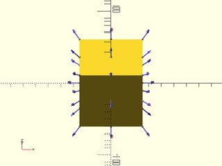
include <BOSL2/std.scad>
cube(50, center=true) show_anchors();
Module: anchor_arrow()
Synopsis: Shows a 3d anchor orientation arrow. [Geom]
Topics: Attachments
See Also: anchor_arrow2d(), show_anchors(), expose_anchors(), frame_ref(), generic_airplane()
Usage:
- anchor_arrow([s], [color], [flag], [anchor=], [orient=], [spin=]) [ATTACHMENTS];
Description:
Show an anchor orientation arrow. By default, tagged with the name "anchor-arrow".
Arguments:
| By Position | What it does |
|---|---|
s |
Length of the arrows. Default: 10 |
color |
Color of the arrow. Default: [0.333, 0.333, 1] |
flag |
If true, draw the orientation flag on the arrowhead. Default: true |
| By Name | What it does |
|---|---|
anchor |
Translate so anchor point is at origin (0,0,0). See anchor. Default: CENTER |
spin |
Rotate this many degrees around the Z axis after anchor. See spin. Default: 0 |
orient |
Vector to rotate top towards, after spin. See orient. Default: UP |
Example 1:
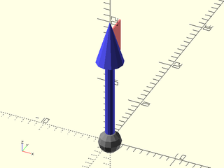
include <BOSL2/std.scad>
anchor_arrow(s=20);
Module: anchor_arrow2d()
Synopsis: Shows a 2d anchor orientation arrow. [Geom]
Topics: Attachments
See Also: anchor_arrow(), show_anchors(), expose_anchors(), frame_ref()
Usage:
- anchor_arrow2d([s], [color]);
Description:
Show an anchor orientation arrow.
Arguments:
| By Position | What it does |
|---|---|
s |
Length of the arrows. |
color |
Color of the arrow. |
Example 1:
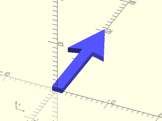
include <BOSL2/std.scad>
anchor_arrow2d(s=20);
Module: expose_anchors()
Synopsis: Used to show a transparent object with solid color anchor arrows.
Topics: Attachments
See Also: anchor_arrow2d(), show_anchors(), show_anchors(), frame_ref()
Usage:
- expose_anchors(opacity) {child1() show_anchors(); child2() show_anchors(); ...}
Description:
Used in combination with show_anchors() to display an object in transparent gray with its anchors in solid color. Children will appear transparent and any anchor arrows drawn with will appear in solid color.
Arguments:
| By Position | What it does |
|---|---|
opacity |
The opacity of the children. 0.0 is invisible, 1.0 is opaque. Default: 0.2 |
Example 1:
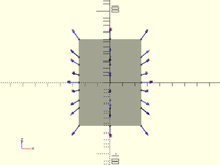
include <BOSL2/std.scad>
expose_anchors() cube(50, center=true) show_anchors();
Module: show_transform_list()
Synopsis: Shows a list of transforms and how they connect. [Geom]
Topics: Attachments
See Also: generic_airplane(), anchor_arrow(), show_anchors(), expose_anchors(), frame_ref()
Usage:
- show_transform_list(tlist, [s]);
- show_transform_list(tlist) {CHILDREN};
Description:
Given a list of transformation matrices, shows the position and orientation of each one.
A line is drawn from each transform position to the next one, and an orientation indicator is
shown at each position. If a child is passed, that child will be used as the orientation indicator.
By default, a generic_airplane() is used as the orientation indicator.
Arguments:
| By Position | What it does |
|---|---|
s |
Length of the generic_airplane(). Default: 5 |
Example 1:
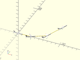
include <BOSL2/std.scad>
tlist = [
    zrot(90),
    zrot(90) * fwd(30) * zrot(30),
    zrot(90) * fwd(30) * zrot(30) *
        fwd(35) * xrot(-30),
    zrot(90) * fwd(30) * zrot(30) *
        fwd(35) * xrot(-30) * fwd(40) * yrot(15),
];
show_transform_list(tlist, s=20);
Example 2:
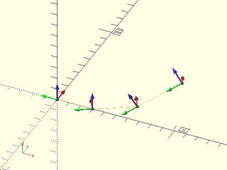
include <BOSL2/std.scad>
tlist = [
    zrot(90),
    zrot(90) * fwd(30) * zrot(30),
    zrot(90) * fwd(30) * zrot(30) *
        fwd(35) * xrot(-30),
    zrot(90) * fwd(30) * zrot(30) *
        fwd(35) * xrot(-30) * fwd(40) * yrot(15),
];
show_transform_list(tlist) frame_ref();
Module: generic_airplane()
Synopsis: Shows a generic airplane shape, useful for viewing orientations. [Geom]
Topics: Attachments
See Also: anchor_arrow(), show_anchors(), expose_anchors(), frame_ref()
Usage:
- generic_airplane([s]);
Description:
Creates a generic airplane shape. This can be useful for viewing the orientation of 3D transforms.
Arguments:
| By Position | What it does |
|---|---|
s |
Length of the airplane. Default: 5 |
Example 1:
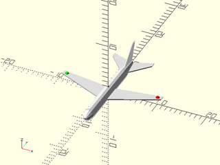
include <BOSL2/std.scad>
generic_airplane(s=20);
Module: frame_ref()
Synopsis: Shows axis orientation arrows. [Geom]
Topics: Attachments
See Also: anchor_arrow(), anchor_arrow2d(), show_anchors(), expose_anchors()
Usage:
- frame_ref(s, opacity);
Description:
Displays X,Y,Z axis arrows in red, green, and blue respectively.
Arguments:
| By Position | What it does |
|---|---|
s |
Length of the arrows. |
opacity |
The opacity of the arrows. 0.0 is invisible, 1.0 is opaque. Default: 1.0 |
Example 1:
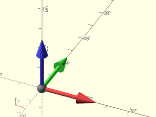
include <BOSL2/std.scad>
frame_ref(25);
Example 2:
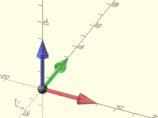
include <BOSL2/std.scad>
frame_ref(30, opacity=0.5);
Section: Attachable Descriptions for Operating on Attachables or Restoring a Previous State
Function: parent()
Synopsis: Returns a description (transformation state and attachment geometry) of the parent
Topics: Transforms, Attachments, Descriptions
See Also: restore()
Usage:
- PARENT() let( desc = parent() ) CHILDREN;
Usage: in development releases only
- PARENT() { desc=parent(); CHILDREN; }
Description:
Returns a description of the closest attachable ancestor in the geometry tree, along with the current transformation. You can use this
description to create new objects based on the described object or perform computations based on the described object. You can also use it to
restore the context of the parent object and transformation state using restore(). Note that with OpenSCAD 2021.01 you need to use let for
this function to work, and the definition of the variable is scoped to the children of the let module.
(In development versions the use of let is no longer necessary.) Note that if OpenSCAD displays any warnings
related to transformation operations then the transformation that parent() returns is likely to be incorrect, even if OpenSCAD
continues to run and produces a valid result.
Module: restore()
Synopsis: Restores transformation state and attachment geometry from a description [Trans]
Topics: Transforms, Attachments, Descriptions
See Also: parent()
Usage:
- restore([desc]) CHILDREN;
Description:
Restores the transformation and parent geometry contained in the specified description which you obtained with parent().
If you don't give a description then restores the global world coordinate system with a zero size cuboid object as the parent.
Arguments:
| By Position | What it does |
|---|---|
desc |
saved description to restore. Default: restore to world coordinates |
Example 1: The pink cube is a child of the green cube, but restore() restores the state to the yellow parent cube, so the pink cube attaches to the yellow cube
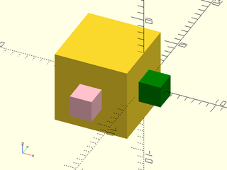
include <BOSL2/std.scad>
left(5) cuboid(10)
  let(save_pt = parent())
  attach(RIGHT,BOT) recolor("green") cuboid(3)
  restore(save_pt)
    attach(FWD,BOT) recolor("pink") cuboid(3);
Indices
Table of Contents
Function Index
Topics Index
Cheat Sheet
Tutorials
List of Files:
Basic Modeling:
- constants.scad STD
- transforms.scad STD
- attachments.scad STD
- shapes2d.scad STD
- shapes3d.scad STD
- drawing.scad STD
- masks2d.scad STD
- masks3d.scad STD
- distributors.scad STD
- color.scad STD
- partitions.scad STD
- miscellaneous.scad STD
Advanced Modeling:
- paths.scad STD
- regions.scad STD
- skin.scad STD
- vnf.scad STD
- beziers.scad
- nurbs.scad
- rounding.scad
- turtle3d.scad
Math:
- math.scad STD
- linalg.scad STD
- vectors.scad STD
- coords.scad STD
- geometry.scad STD
- trigonometry.scad STD
Data Management:
- version.scad STD
- comparisons.scad STD
- lists.scad STD
- utility.scad STD
- strings.scad STD
- structs.scad STD
- fnliterals.scad
Threaded Parts:
Parts:
- ball_bearings.scad
- cubetruss.scad
- gears.scad
- hinges.scad
- joiners.scad
- linear_bearings.scad
- modular_hose.scad
- nema_steppers.scad
- polyhedra.scad
- sliders.scad
- tripod_mounts.scad
- walls.scad
- wiring.scad
Footnotes:
STD = Included in std.scad